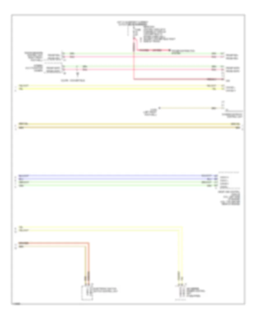
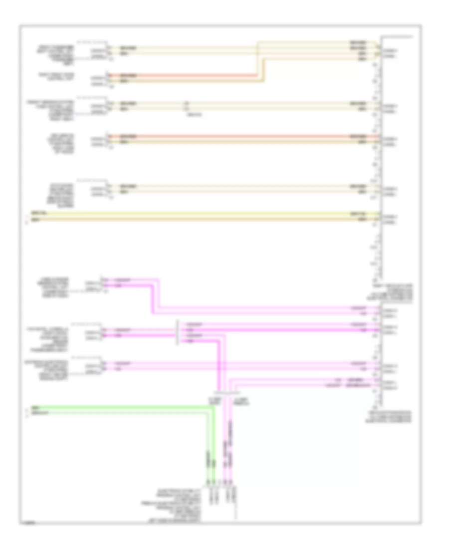
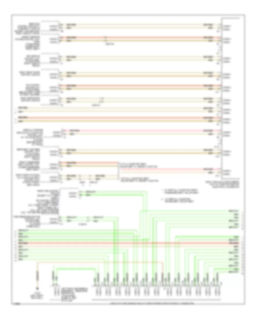
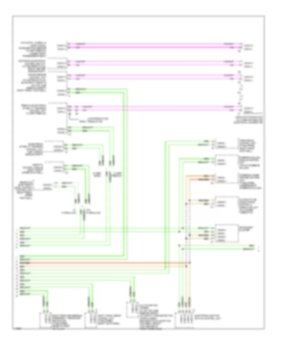
COMPUTER DATA LINES
Data Link Connector Wiring Diagram for Mercedes-Benz E350 2013

List of elements for Data Link Connector Wiring Diagram for Mercedes-Benz E350 2013:
- 31e
- C15h
- C19i
- C22i
- Can d h
- Can d l
- Coupe
- Diagnostic connector (under left side of dash)
- Electronic stability program control unit (w/ esp basic) premium electronic stability program control unit (w/ esp premium) (w/ esp basic: left side of engine compt)
- Front sam control module w/ fuse/ relay module (left rear of engine compt)
- Fuse 7.5a 5a
- Hot at all times
- Power distribution system
- Rear sam control module w/ fuse/ relay module (convertible: in spare wheelwell) (except convertible: right side of trunk)
- Sedan
- W/ esp basic
- W/ esp premium
- W15/5 (coupe) w15/2 (sedan) (left front footwell)
- W3/1 (diesel) w16/5 (gasoline) (diesel: behind right front fender) (gasoline: left rear of engine compt)
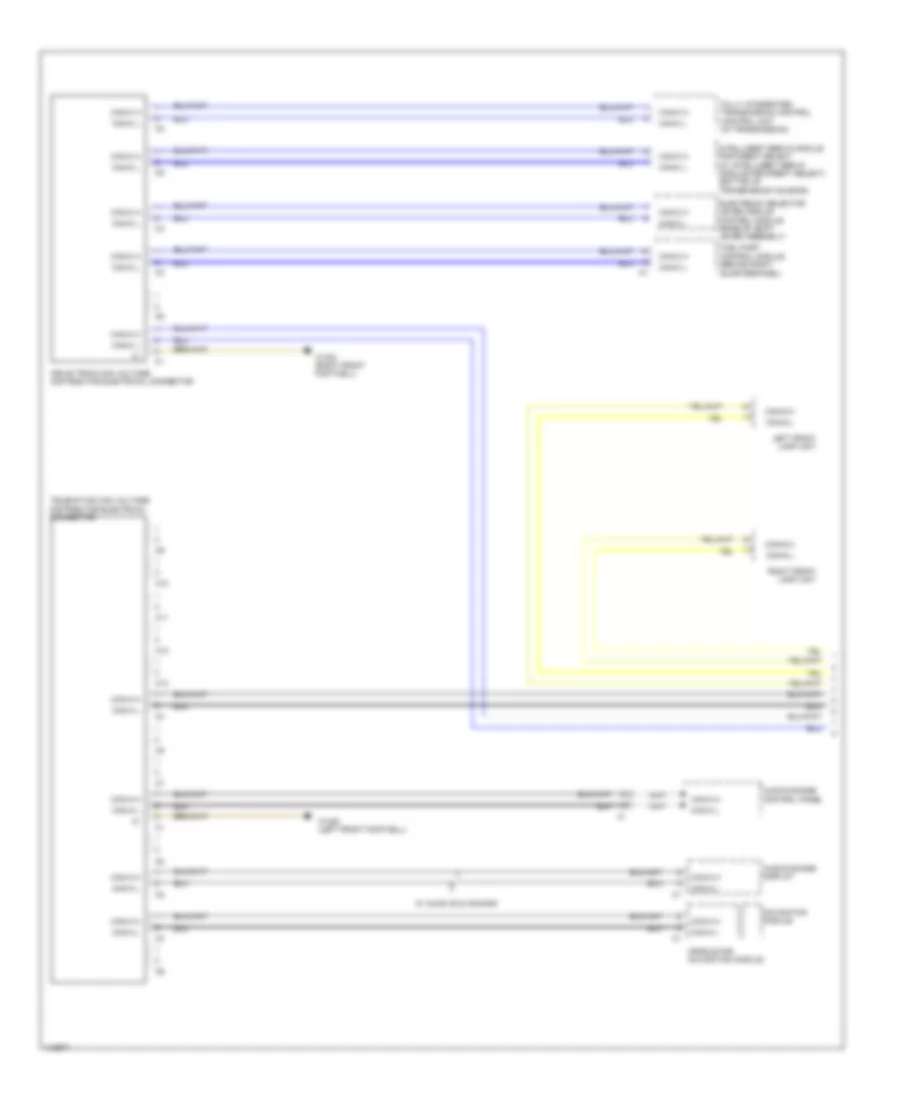
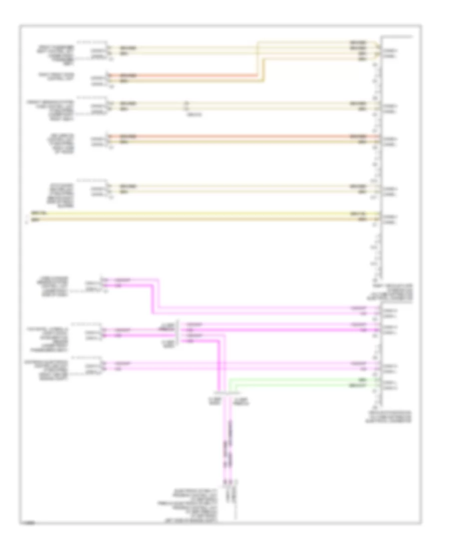
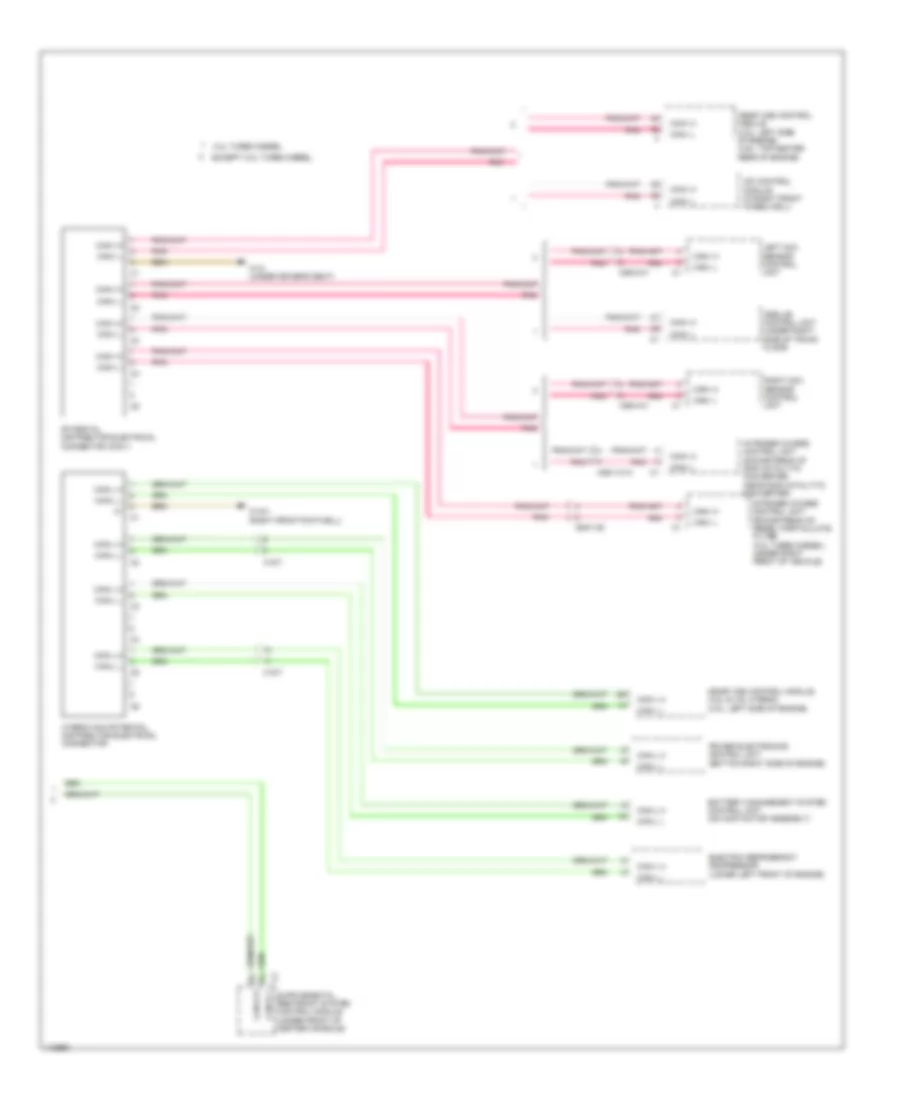
High/Low Bus Wiring Diagram, Convertible Early Production without CAN E1 (1 of 5) for Mercedes-Benz E350 2013
List of elements for High/Low Bus Wiring Diagram, Convertible Early Production without CAN E1 (1 of 5) for Mercedes-Benz E350 2013:
- Audio/comand control panel
- Audio/comand display
- C10
- C11
- C12
- C13
- Can-a h
- Can-a l
- Can-c h
- Can-c l
- Can-g h
- Can-g l
- Cradle for navigation module
- Drive train can voltage distributor electrical connector
- Electronic selector lever module control module (base of shift lever assembly)
- Fuel pump control module (behind right quarterpanel)
- Fully integrated transmission control control unit (in transmission)
- Intelligent servo module for direct select (w/ intelligent servo module for direct select) (bottom of transmission housing)
- Left front lamp unit
- Navigation module
- Right front lamp unit
- Telematics can voltage distributor electrical connector
- W/ audio 20 & comand
- W15/6 (left front footwell)
- W15/8 (right front footwell)
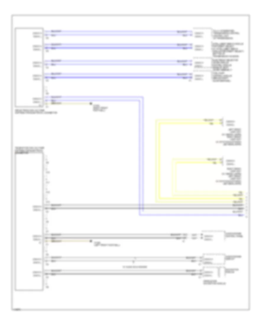
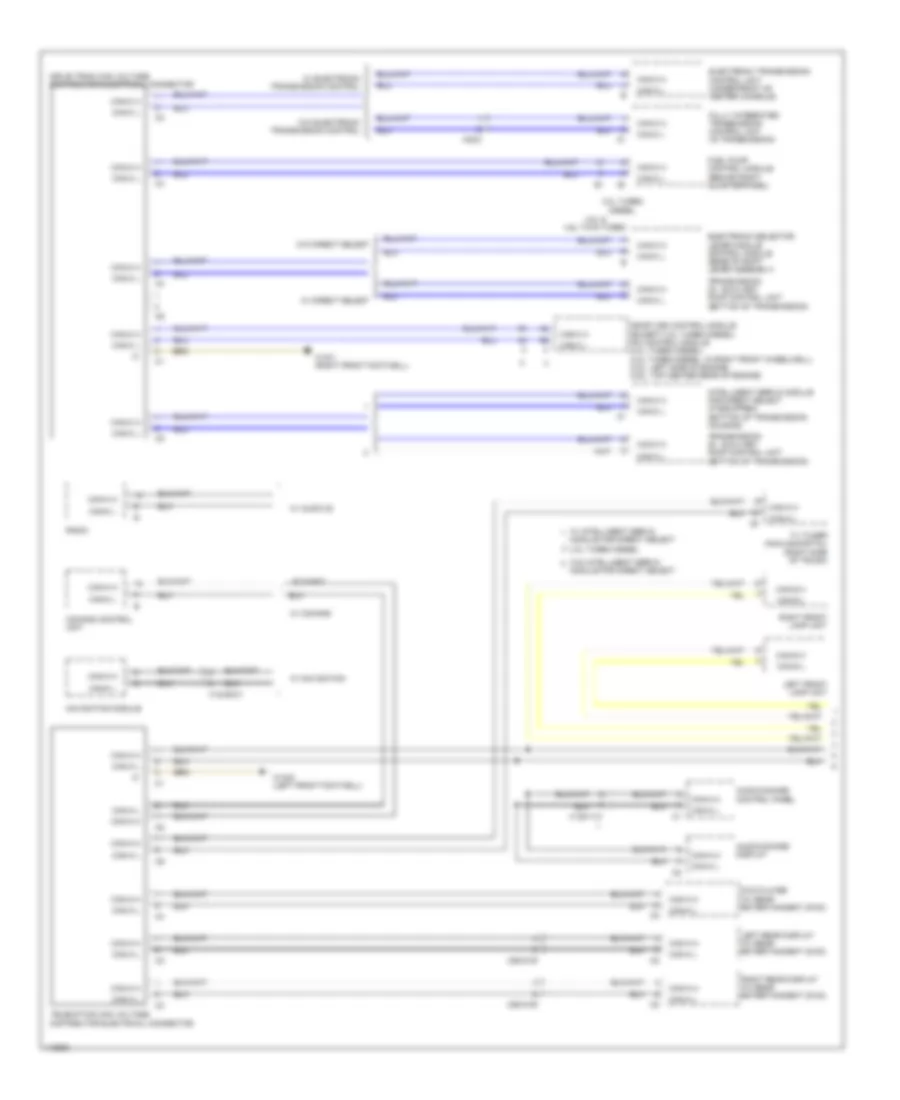
High/Low Bus Wiring Diagram, Convertible Early Production without CAN E1 (2 of 5) for Mercedes-Benz E350 2013
List of elements for High/Low Bus Wiring Diagram, Convertible Early Production without CAN E1 (2 of 5) for Mercedes-Benz E350 2013:
- Air scarf system control unit (right side of trunk)
- Automatic air conditioning control & operating unit
- C10
- C10t
- C11
- C12
- C13
- C18m
- C19i
- C20m
- C21m
- C22i
- C2i
- C4i
- C5h
- C9i
- Can-a h
- Can-a l
- Can-b h
- Can-b l
- Can-c h
- Can-c l
- Can-d h
- Can-d l
- Can-e h
- Can-e l
- Can-e1 h
- Can-e1 l
- Can-g h
- Can-g l
- Comand control unit
- Driver seat control unit (under driver front seat)
- Emergency call system control unit (w/ teleaid emergency call system) (center front of trunk)
- Front sam control module w/ fuse/ relay module (left rear of engine compt)
- Left front door control module
- Left rear bumper intelligent radar sensor (behind left side of rear bumper)
- Left vehicle floor interior can voltage distributor electrical connector
- Panoramic sliding roof control module (integral to panoramic sliding roof drive unit)
- Pnk
- Radio
- Rear control module (convertible: right front of trunk) (except convertible: left front of trunk)
- Rear sam control module w/ fuse/relay module (convertible: in spare wheelwell) (except convertible: right side of trunk)
- Right rear bumper intelligent radar sensor (behind right side of rear bumper)
- Trailer recognition control unit (convertible: in spare wheelwell) (except convertible: right side of trunk)
- W/ audio 20
- W/o audio 20
- W15/6 (left front footwell)
- X204
- X35/28
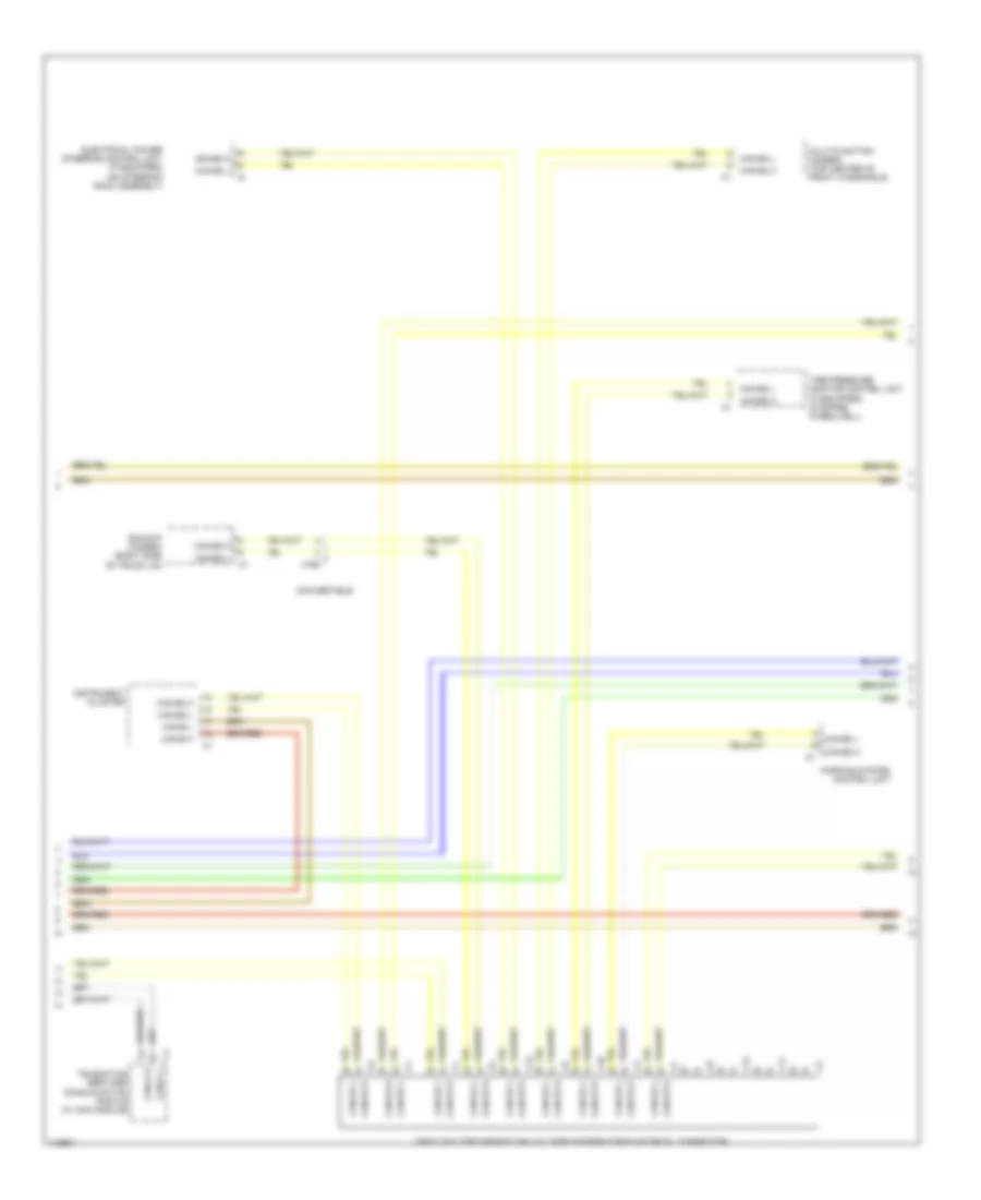
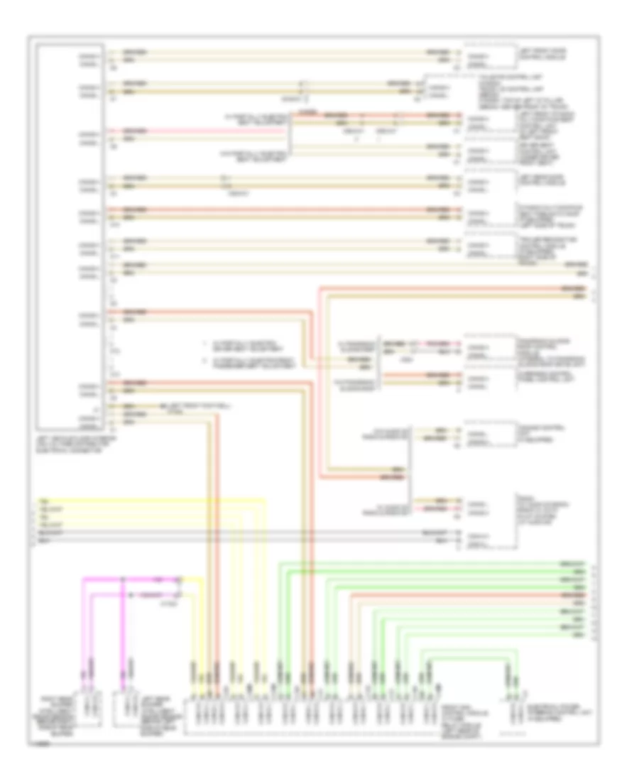
High/Low Bus Wiring Diagram, Convertible Early Production without CAN E1 (3 of 5) for Mercedes-Benz E350 2013
List of elements for High/Low Bus Wiring Diagram, Convertible Early Production without CAN E1 (3 of 5) for Mercedes-Benz E350 2013:
- 360 degree camera control unit (if equipped)
- C10
- C11
- C12
- C13
- Can-b h
- Can-b l
- Can-d h
- Can-d l
- Can-e h
- Can-e l
- Can-e l left front reversible emergency tensioning retractor (if equipped) (base of left front "b" pillar)
- Can-e1 h
- Can-e1 l
- Electrical power steering control unit (if equipped) (on steering rack assembly)
- Instrument cluster
- Steering column module control unit (top of steering column)
- Telematics services communication module (w/ com module)
- Tire pressure monitor control unit (if equipped) (in spare wheelwell)
- Vehicle floor chassis can voltage distributor electrical connector
- W15/6 (left front footwell)
High/Low Bus Wiring Diagram, Convertible Early Production without CAN E1 (4 of 5) for Mercedes-Benz E350 2013
List of elements for High/Low Bus Wiring Diagram, Convertible Early Production without CAN E1 (4 of 5) for Mercedes-Benz E350 2013:
- Adaptive damping system control unit (if equipped)
- Can-b h
- Can-b l
- Can-c h
- Can-c l
- Can-e h
- Can-e l
- Can-e1 h
- Can-e1 l
- Can-h h
- Can-h l
- Electronic ignition switch control unit
- Me-sfi (me) control module (3.5l: left side of engine) (4.6l: top center rear of engine)
- Multi-function camera (w/ adaptive highbeam assist) (top center of front windshield)
- Parking system control unit
- Right front reversible emergency tensioning retractor (if equipped) (base of right front "b" pillar)
- Video & radar sensor system control unit (under right side of dash)
- W/ parktronic
- W/o parktronic
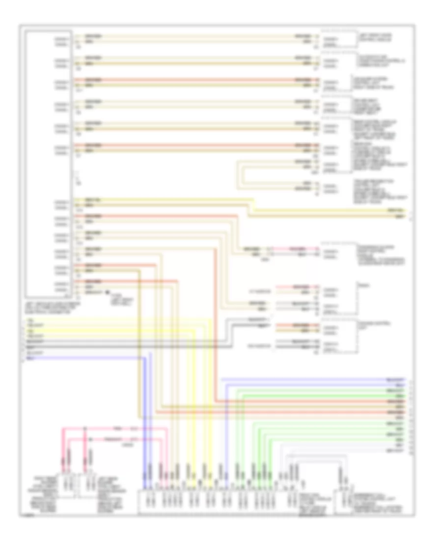
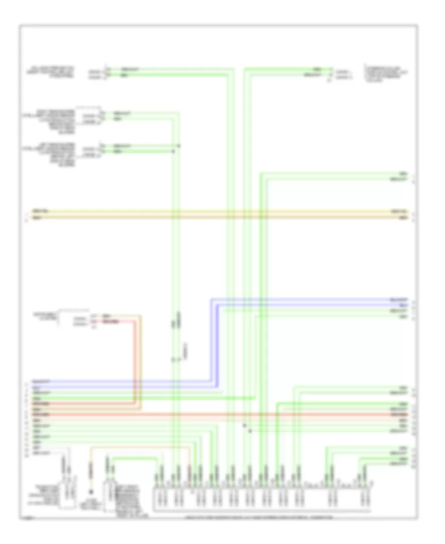
High/Low Bus Wiring Diagram, Convertible Early Production without CAN E1 (5 of 5) for Mercedes-Benz E350 2013
List of elements for High/Low Bus Wiring Diagram, Convertible Early Production without CAN E1 (5 of 5) for Mercedes-Benz E350 2013:
- C10
- C11
- C12
- C13
- Can-b h
- Can-b l
- Can-e h
- Can-e l
- Can-h h
- Can-h l
- Distronic electronic controller unit (if equipped) (front center engine compt)
- Electronic stability program control unit (w/ esp basic) premium electronic stability program control unit (w/ esp premium) (w/ esp basic: left side of engine compt)
- Front passenger seat control unit (under front passenger seat)
- Keyless go control unit (if equipped) (right side of trunk)
- Right front door control unit
- Right vehicle floor interior can voltage distributor electrical connector
- Stationary heater unit (if equipped) (behind right side of front bumper)
- Vehicle dynamics can voltage distributor electrical connector
- W/ esp basic
- W/ esp premium
- Weight sensing system (wss) control unit (if equipped) (under right front seat)
- X55/4-c2
- Yaw rate, lateral & longitudinal acceleration sensor (under front passenger's seat)
High/Low Bus Wiring Diagram, Convertible Late Production without CAN E1 (1 of 5) for Mercedes-Benz E350 2013
List of elements for High/Low Bus Wiring Diagram, Convertible Late Production without CAN E1 (1 of 5) for Mercedes-Benz E350 2013:
- Audio/comand control panel
- Audio/comand display
- C10
- C11
- C12
- C13
- Can-a h
- Can-a l
- Can-c h
- Can-c l
- Can-g h
- Can-g l
- Cradle for navigation module
- Drive train can voltage distributor electrical connector
- Electronic selector lever module control module (base of shift lever assembly)
- Fuel pump control module (behind right quarterpanel)
- Fully integrated transmission control control unit (in transmission)
- Intelligent servo module for direct select (w/ intelligent servo module for direct select) (bottom of transmission housing)
- Left front lamp unit
- Navigation module
- Right front lamp unit
- Telematics can voltage distributor electrical connector
- W/ audio 20 & comand
- W15/6 (left front footwell)
- W15/8 (right front footwell)
High/Low Bus Wiring Diagram, Convertible Late Production without CAN E1 (2 of 5) for Mercedes-Benz E350 2013
List of elements for High/Low Bus Wiring Diagram, Convertible Late Production without CAN E1 (2 of 5) for Mercedes-Benz E350 2013:
- Air scarf system control unit (right side of trunk)
- Automatic air conditioning control & operating unit
- C10
- C10t
- C11
- C12
- C13
- C18m
- C20m
- C21m
- C22i
- C2i
- C4i
- C5h
- C9i
- Can-a h
- Can-a l
- Can-b h
- Can-b l
- Can-c h
- Can-c l
- Can-d h
- Can-d l
- Can-e1 h
- Can-e1 l
- Can-e2 h
- Can-e2 l
- Can-g h
- Can-g l
- Comand control unit
- Driver seat control unit (under driver front seat)
- Emergency call system control unit (w/ teleaid emergency call system) (center front of trunk)
- Front sam control module w/ fuse/ relay module (left rear of engine compt)
- Left front door control module
- Left vehicle floor interior can voltage distributor electrical connector
- Panoramic sliding roof control module (integral to panoramic sliding roof drive unit)
- Radio
- Rear control module (convertible: right front of trunk) (except convertible: left front of trunk)
- Rear sam control module w/ fuse/relay module (convertible: in spare wheelwell) (except convertible: right side of trunk)
- Trailer recognition control unit (convertible: in spare wheelwell) (except convertible: right side of trunk)
- W/ audio 20
- W/o audio 20
- W15/6 (left front footwell)
- X204
High/Low Bus Wiring Diagram, Convertible Late Production without CAN E1 (3 of 5) for Mercedes-Benz E350 2013
List of elements for High/Low Bus Wiring Diagram, Convertible Late Production without CAN E1 (3 of 5) for Mercedes-Benz E350 2013:
- Backup camera (right side of trunk lid)
- C10
- C11
- C12
- C13
- Can-b h
- Can-b l
- Can-d h
- Can-d l
- Can-e2 h
- Can-e2 l
- Convertible
- Electrical power steering control unit (if equipped) (on steering rack assembly)
- Instrument cluster
- Multi-function camera (top center of front windshield)
- Parking system control unit
- Telematics services communication module (w/ com module)
- Tire pressure monitor control unit (if equipped) (in spare wheelwell)
- Vehicle floor chassis can voltage distributor electrical connector
- X169
High/Low Bus Wiring Diagram, Convertible Late Production without CAN E1 (4 of 5) for Mercedes-Benz E350 2013
List of elements for High/Low Bus Wiring Diagram, Convertible Late Production without CAN E1 (4 of 5) for Mercedes-Benz E350 2013:
- (or red)
- 30g
- 360 degree camera control unit (if equipped)
- C14i
- Can e2 h
- Can e2 l
- Can-b h
- Can-b l
- Can-c h
- Can-c l
- Can-e h
- Can-e l
- Can-e2 h
- Can-e2 l
- Chassis gateway control unit
- Convertible
- Coupe
- Electronic ignition switch control unit
- Fr2-bm smpc
- Fr2-bp smpc
- Fr3-bm rdu
- Fr3-bp rdu
- Fuse 5a
- Hot w/ quiescent current cutout relay energized
- Me-sfi (me) control module (3.5l: left side of engine) (4.6l: top center rear of engine)
- Pnk
- Pnk/red
- Power distribution system
- Radar sensors control unit (right front footwell)
- Rear sam control module w/ fuse/relay module (convertible: in spare wheelwell) (except convertible: right side of trunk)
- Stereo multi-function camera
- W15/6 (left front footwell)
High/Low Bus Wiring Diagram, Convertible Late Production without CAN E1 (5 of 5) for Mercedes-Benz E350 2013
List of elements for High/Low Bus Wiring Diagram, Convertible Late Production without CAN E1 (5 of 5) for Mercedes-Benz E350 2013:
- C10
- C11
- C12
- C13
- Can-b h
- Can-b l
- Can-h h
- Can-h l
- Distronic electronic controller unit (if equipped) (front center engine compt)
- Electronic stability program control unit (w/ esp basic) premium electronic stability program control unit (w/ esp premium) (w/ esp basic: left side of engine compt)
- Front passenger seat control unit (under front passenger seat)
- Keyless go control unit (if equipped) (right side of trunk)
- Right front door control unit
- Right vehicle floor interior can voltage distributor electrical connector
- Stationary heater unit (if equipped) (behind right side of front bumper)
- Vehicle dynamics can voltage distributor electrical connector
- Video & radar sensor system control unit (under right side of dash)
- W/ esp basic
- W/ esp premium
- Weight sensing system (wss) control unit (if equipped) (under right front seat)
- X55/4-c2
- Yaw rate, lateral & longitudinal acceleration sensor (under front passenger's seat)
High/Low Bus Wiring Diagram, Convertible with CAN E1 (1 of 5) for Mercedes-Benz E350 2013
List of elements for High/Low Bus Wiring Diagram, Convertible with CAN E1 (1 of 5) for Mercedes-Benz E350 2013:
- Audio/comand control panel
- Audio/comand display
- C10
- C11
- C12
- C13
- Can-a h
- Can-a l
- Can-c h
- Can-c l
- Can-g h
- Can-g l
- Cradle for navigation module
- Drive train can voltage distributor electrical connector
- Electronic selector lever module control module (base of shift lever assembly)
- Fuel pump control module (behind right quarterpanel)
- Fully integrated transmission control control unit (in transmission)
- Intelligent servo module for direct select (w/ intelligent servo module for direct select) (bottom of transmission housing)
- Left front lamp unit (w/ xenon lamps) right front lamp unit (w/ statics & dynamic led headlamps)
- Navigation module
- Right front lamp unit (w/ xenon lamps) left front lamp unit (w/ statics & dynamic led headlamps)
- Telematics can voltage distributor electrical connector
- W/ audio 20 & comand
- W15/6 (left front footwell)
- W15/8 (right front footwell)
High/Low Bus Wiring Diagram, Convertible with CAN E1 (2 of 5) for Mercedes-Benz E350 2013
List of elements for High/Low Bus Wiring Diagram, Convertible with CAN E1 (2 of 5) for Mercedes-Benz E350 2013:
- Air scarf system control unit (right side of trunk)
- Automatic air conditioning control & operating unit
- C10
- C10t
- C11
- C12
- C13
- C18m
- C19i
- C20m
- C21m
- C22i
- C2i
- C4i
- C5h
- C9i
- Can-a h
- Can-a l
- Can-b h
- Can-b l
- Can-c h
- Can-c l
- Can-d h
- Can-d l
- Can-e1 h
- Can-e1 l
- Can-g h
- Can-g l
- Comand control unit
- Driver seat control unit (under driver front seat)
- Emergency call system control unit (w/ teleaid emergency call system) (center front of trunk)
- Front sam control module w/ fuse/ relay module (left rear of engine compt)
- Left front door control module
- Left rear bumper intelligent radar sensor (early production) (behind left side of rear bumper)
- Left vehicle floor interior can voltage distributor electrical connector
- Panoramic sliding roof control module (integral to panoramic sliding roof drive unit)
- Pnk
- Radio
- Rear control module (convertible: right front of trunk) (except convertible: left front of trunk)
- Rear sam control module w/ fuse/relay module (convertible: in spare wheelwell) (except convertible: right side of trunk)
- Right rear bumper intelligent radar sensor (early production) (behind right side of rear bumper)
- Trailer recognition control unit (convertible: in spare wheelwell) (except convertible: right side of trunk)
- W/ audio 20
- W/o audio 20
- W15/6 (left front footwell)
- X204
- X35/28
High/Low Bus Wiring Diagram, Convertible with CAN E1 (3 of 5) for Mercedes-Benz E350 2013
List of elements for High/Low Bus Wiring Diagram, Convertible with CAN E1 (3 of 5) for Mercedes-Benz E350 2013:
- C10
- C11
- C12
- C13
- Can-b h
- Can-b l
- Can-d h
- Can-d l
- Can-e1 h
- Can-e1 l
- Can-e1 l left front reversible emergency tensioning retractor (if equipped) (base of left front "b" pillar)
- Collision prevention assist controller unit (if equipped)
- Instrument cluster
- Left rear bumper intelligent radar sensor (late production) (behind left side of rear bumper)
- Right rear bumper intelligent radar sensor (late production) (behind right side of rear bumper)
- Steering column module control unit (top of steering column)
- Telematics services communication module (w/ com module)
- Vehicle floor chassis can e1 voltage distributor electrical connector
- W15/6 (left front footwell)
- X35/28-c2
High/Low Bus Wiring Diagram, Convertible with CAN E1 (4 of 5) for Mercedes-Benz E350 2013
List of elements for High/Low Bus Wiring Diagram, Convertible with CAN E1 (4 of 5) for Mercedes-Benz E350 2013:
- (or red)
- 30g
- Adaptive damping system control unit (if equipped)
- C14i
- Can
- Can e1 h
- Can e1 l
- Can-b h
- Can-b l
- Can-c h
- Can-c l
- Can-e h
- Can-e l
- Can-e1 h
- Can-e1 l
- Chassis gateway control unit
- Convertible
- Coupe
- Electronic ignition switch control unit
- Fr2-bm smpc
- Fr2-bp smpc
- Fr3-bm rdu
- Fr3-bp rdu
- Fuse 5a
- Hot w/ quiescent current cutout relay energized
- Me-sfi (me) control module (3.5l: left side of engine) (4.6l: top center rear of engine)
- Pnk
- Pnk/red
- Power distribution system
- Radar sensors control unit (right front footwell)
- Rear sam control module w/ fuse/relay module (convertible: in spare wheelwell) (except convertible: right side of trunk)
- Right front reversible emergency tensioning retractor (if equipped) (base of right front "b" pillar)
- Stereo multi-function camera
- W15/6 (left front footwell)
High/Low Bus Wiring Diagram, Convertible with CAN E1 (5 of 5) for Mercedes-Benz E350 2013
List of elements for High/Low Bus Wiring Diagram, Convertible with CAN E1 (5 of 5) for Mercedes-Benz E350 2013:
- C10
- C11
- C12
- C13
- Can-b h
- Can-b l
- Can-e1 h
- Can-e1 l
- Can-h h
- Can-h l
- Distronic electronic controller unit (if equipped) (front center engine compt)
- Electronic stability program control unit (w/ esp basic) premium electronic stability program control unit (w/ esp premium) (w/ esp basic: left side of engine compt)
- Front passenger seat control unit (under front passenger seat)
- Keyless go control unit (if equipped) (right side of trunk)
- Right front door control unit
- Right vehicle floor interior can voltage distributor electrical connector
- Stationary heater unit (if equipped) (behind right side of front bumper)
- Vehicle dynamics can voltage distributor electrical connector
- Video & radar sensor system control unit (under right side of dash)
- W/ esp basic
- W/ esp premium
- Weight sensing system (wss) control unit (if equipped) (under right front seat)
- X55/4-c2
- Yaw rate, lateral & longitudinal acceleration sensor (under front passenger's seat)
High/Low Bus Wiring Diagram, Coupe Early Production without CAN E1 (1 of 5) for Mercedes-Benz E350 2013
List of elements for High/Low Bus Wiring Diagram, Coupe Early Production without CAN E1 (1 of 5) for Mercedes-Benz E350 2013:
- Audio/comand control panel
- Audio/comand display
- C10
- C11
- C12
- C13
- Can-a h
- Can-a l
- Can-c h
- Can-c l
- Can-g h
- Can-g l
- Cradle for navigation module
- Drive train can voltage distributor electrical connector
- Electronic selector lever module control module (base of shift lever assembly)
- Fuel pump control module (behind right quarterpanel)
- Fully integrated transmission control control unit (in transmission)
- Intelligent servo module for direct select (w/ intelligent servo module for direct select) (bottom of transmission housing)
- Left front lamp unit
- Navigation module
- Right front lamp unit
- Telematics can voltage distributor electrical connector
- W/ audio 20 & comand
- W15/6 (left front footwell)
- W15/8 (right front footwell)
High/Low Bus Wiring Diagram, Coupe Early Production without CAN E1 (2 of 5) for Mercedes-Benz E350 2013
List of elements for High/Low Bus Wiring Diagram, Coupe Early Production without CAN E1 (2 of 5) for Mercedes-Benz E350 2013:
- Air scarf system control unit (right side of trunk)
- Automatic air conditioning control & operating unit
- C10
- C10t
- C11
- C12
- C13
- C18m
- C19i
- C20m
- C21m
- C22i
- C2i
- C4i
- C5h
- C9i
- Can-a h
- Can-a l
- Can-b h
- Can-b l
- Can-c h
- Can-c l
- Can-d h
- Can-d l
- Can-e h
- Can-e l
- Can-e1 h
- Can-e1 l
- Can-g h
- Can-g l
- Comand control unit
- Driver seat control unit (under driver front seat)
- Emergency call system control unit (w/ teleaid emergency call system) (center front of trunk)
- Front sam control module w/ fuse/ relay module (left rear of engine compt)
- Left front door control module
- Left rear bumper intelligent radar sensor (behind left side of rear bumper)
- Left vehicle floor interior can voltage distributor electrical connector
- Panoramic sliding roof control module (integral to panoramic sliding roof drive unit)
- Pnk
- Radio
- Rear control module (convertible: right front of trunk) (except convertible: left front of trunk)
- Rear sam control module w/ fuse/relay module (convertible: in spare wheelwell) (except convertible: right side of trunk)
- Right rear bumper intelligent radar sensor (behind right side of rear bumper)
- Trailer recognition control unit (convertible: in spare wheelwell) (except convertible: right side of trunk)
- W/ audio 20
- W/o audio 20
- W15/6 (left front footwell)
- X204
- X35/28
High/Low Bus Wiring Diagram, Coupe Early Production without CAN E1 (3 of 5) for Mercedes-Benz E350 2013
List of elements for High/Low Bus Wiring Diagram, Coupe Early Production without CAN E1 (3 of 5) for Mercedes-Benz E350 2013:
- 360 degree camera control unit (if equipped)
- C10
- C11
- C12
- C13
- Can-b h
- Can-b l
- Can-d h
- Can-d l
- Can-e h
- Can-e l
- Can-e l left front reversible emergency tensioning retractor (if equipped) (base of left front "b" pillar)
- Can-e1 h
- Can-e1 l
- Electrical power steering control unit (if equipped) (on steering rack assembly)
- Instrument cluster
- Steering column module control unit (top of steering column)
- Telematics services communication module (w/ com module)
- Tire pressure monitor control unit (if equipped) (in spare wheelwell)
- Vehicle floor chassis can voltage distributor electrical connector
- W15/6 (left front footwell)
High/Low Bus Wiring Diagram, Coupe Early Production without CAN E1 (4 of 5) for Mercedes-Benz E350 2013
List of elements for High/Low Bus Wiring Diagram, Coupe Early Production without CAN E1 (4 of 5) for Mercedes-Benz E350 2013:
- Adaptive damping system control unit (if equipped)
- Can-b h
- Can-b l
- Can-c h
- Can-c l
- Can-e h
- Can-e l
- Can-e1 h
- Can-e1 l
- Can-h h
- Can-h l
- Electronic ignition switch control unit
- Me-sfi (me) control module (3.5l: left side of engine) (4.6l: top center rear of engine)
- Multi-function camera (w/ adaptive highbeam assist) (top center of front windshield)
- Parking system control unit
- Right front reversible emergency tensioning retractor (if equipped) (base of right front "b" pillar)
- Video & radar sensor system control unit (under right side of dash)
- W/ parktronic
- W/o parktronic
High/Low Bus Wiring Diagram, Coupe Early Production without CAN E1 (5 of 5) for Mercedes-Benz E350 2013
List of elements for High/Low Bus Wiring Diagram, Coupe Early Production without CAN E1 (5 of 5) for Mercedes-Benz E350 2013:
- C10
- C11
- C12
- C13
- Can-b h
- Can-b l
- Can-e h
- Can-e l
- Can-h h
- Can-h l
- Distronic electronic controller unit (if equipped) (front center engine compt)
- Electronic stability program control unit (w/ esp basic) premium electronic stability program control unit (w/ esp premium) (w/ esp basic: left side of engine compt)
- Front passenger seat control unit (under front passenger seat)
- Keyless go control unit (if equipped) (right side of trunk)
- Right front door control unit
- Right vehicle floor interior can voltage distributor electrical connector
- Stationary heater unit (if equipped) (behind right side of front bumper)
- Vehicle dynamics can voltage distributor electrical connector
- W/ esp basic
- W/ esp premium
- Weight sensing system (wss) control unit (if equipped) (under right front seat)
- X55/4-c2
- Yaw rate, lateral & longitudinal acceleration sensor (under front passenger's seat)
High/Low Bus Wiring Diagram, Coupe Late Production without CAN E1 (1 of 5) for Mercedes-Benz E350 2013
List of elements for High/Low Bus Wiring Diagram, Coupe Late Production without CAN E1 (1 of 5) for Mercedes-Benz E350 2013:
- Audio/comand control panel
- Audio/comand display
- C10
- C11
- C12
- C13
- Can-a h
- Can-a l
- Can-c h
- Can-c l
- Can-g h
- Can-g l
- Cradle for navigation module
- Drive train can voltage distributor electrical connector
- Electronic selector lever module control module (base of shift lever assembly)
- Fuel pump control module (behind right quarterpanel)
- Fully integrated transmission control control unit (in transmission)
- Intelligent servo module for direct select (w/ intelligent servo module for direct select) (bottom of transmission housing)
- Left front lamp unit
- Navigation module
- Right front lamp unit
- Telematics can voltage distributor electrical connector
- W/ audio 20 & comand
- W15/6 (left front footwell)
- W15/8 (right front footwell)
High/Low Bus Wiring Diagram, Coupe Late Production without CAN E1 (2 of 5) for Mercedes-Benz E350 2013
List of elements for High/Low Bus Wiring Diagram, Coupe Late Production without CAN E1 (2 of 5) for Mercedes-Benz E350 2013:
- Air scarf system control unit (right side of trunk)
- Automatic air conditioning control & operating unit
- C10
- C10t
- C11
- C12
- C13
- C18m
- C20m
- C21m
- C22i
- C2i
- C4i
- C5h
- C9i
- Can-a h
- Can-a l
- Can-b h
- Can-b l
- Can-c h
- Can-c l
- Can-d h
- Can-d l
- Can-e1 h
- Can-e1 l
- Can-e2 h
- Can-e2 l
- Can-g h
- Can-g l
- Comand control unit
- Driver seat control unit (under driver front seat)
- Emergency call system control unit (w/ teleaid emergency call system) (center front of trunk)
- Front sam control module w/ fuse/ relay module (left rear of engine compt)
- Left front door control module
- Left vehicle floor interior can voltage distributor electrical connector
- Panoramic sliding roof control module (integral to panoramic sliding roof drive unit)
- Radio
- Rear control module (convertible: right front of trunk) (except convertible: left front of trunk)
- Rear sam control module w/ fuse/relay module (convertible: in spare wheelwell) (except convertible: right side of trunk)
- Trailer recognition control unit (convertible: in spare wheelwell) (except convertible: right side of trunk)
- W/ audio 20
- W/o audio 20
- W15/6 (left front footwell)
- X204
High/Low Bus Wiring Diagram, Coupe Late Production without CAN E1 (3 of 5) for Mercedes-Benz E350 2013
List of elements for High/Low Bus Wiring Diagram, Coupe Late Production without CAN E1 (3 of 5) for Mercedes-Benz E350 2013:
- Backup camera (right side of trunk lid)
- C10
- C11
- C12
- C13
- Can-b h
- Can-b l
- Can-d h
- Can-d l
- Can-e2 h
- Can-e2 l
- Convertible
- Electrical power steering control unit (if equipped) (on steering rack assembly)
- Instrument cluster
- Multi-function camera (top center of front windshield)
- Parking system control unit
- Telematics services communication module (w/ com module)
- Tire pressure monitor control unit (if equipped) (in spare wheelwell)
- Vehicle floor chassis can voltage distributor electrical connector
- X169
High/Low Bus Wiring Diagram, Coupe Late Production without CAN E1 (4 of 5) for Mercedes-Benz E350 2013
List of elements for High/Low Bus Wiring Diagram, Coupe Late Production without CAN E1 (4 of 5) for Mercedes-Benz E350 2013:
- (or red)
- 30g
- 360 degree camera control unit (if equipped)
- C14i
- Can e2 h
- Can e2 l
- Can-b h
- Can-b l
- Can-c h
- Can-c l
- Can-e h
- Can-e l
- Can-e2 h
- Can-e2 l
- Chassis gateway control unit
- Convertible
- Coupe
- Electronic ignition switch control unit
- Fr2-bm smpc
- Fr2-bp smpc
- Fr3-bm rdu
- Fr3-bp rdu
- Fuse 5a
- Hot w/ quiescent current cutout relay energized
- Me-sfi (me) control module (3.5l: left side of engine) (4.6l: top center rear of engine)
- Pnk
- Pnk/red
- Power distribution system
- Radar sensors control unit (right front footwell)
- Rear sam control module w/ fuse/relay module (convertible: in spare wheelwell) (except convertible: right side of trunk)
- Stereo multi-function camera
- W15/6 (left front footwell)
High/Low Bus Wiring Diagram, Coupe Late Production without CAN E1 (5 of 5) for Mercedes-Benz E350 2013
List of elements for High/Low Bus Wiring Diagram, Coupe Late Production without CAN E1 (5 of 5) for Mercedes-Benz E350 2013:
- C10
- C11
- C12
- C13
- Can-b h
- Can-b l
- Can-h h
- Can-h l
- Distronic electronic controller unit (if equipped) (front center engine compt)
- Electronic stability program control unit (w/ esp basic) premium electronic stability program control unit (w/ esp premium) (w/ esp basic: left side of engine compt)
- Front passenger seat control unit (under front passenger seat)
- Keyless go control unit (if equipped) (right side of trunk)
- Right front door control unit
- Right vehicle floor interior can voltage distributor electrical connector
- Stationary heater unit (if equipped) (behind right side of front bumper)
- Vehicle dynamics can voltage distributor electrical connector
- Video & radar sensor system control unit (under right side of dash)
- W/ esp basic
- W/ esp premium
- Weight sensing system (wss) control unit (if equipped) (under right front seat)
- X55/4-c2
- Yaw rate, lateral & longitudinal acceleration sensor (under front passenger's seat)
High/Low Bus Wiring Diagram, Coupe with CAN E1 (1 of 5) for Mercedes-Benz E350 2013
List of elements for High/Low Bus Wiring Diagram, Coupe with CAN E1 (1 of 5) for Mercedes-Benz E350 2013:
- Audio/comand control panel
- Audio/comand display
- C10
- C11
- C12
- C13
- Can-a h
- Can-a l
- Can-c h
- Can-c l
- Can-g h
- Can-g l
- Cradle for navigation module
- Drive train can voltage distributor electrical connector
- Electronic selector lever module control module (base of shift lever assembly)
- Fuel pump control module (behind right quarterpanel)
- Fully integrated transmission control control unit (in transmission)
- Intelligent servo module for direct select (w/ intelligent servo module for direct select) (bottom of transmission housing)
- Left front lamp unit (w/ xenon lamps) right front lamp unit (w/ statics & dynamic led headlamps)
- Navigation module
- Right front lamp unit (w/ xenon lamps) left front lamp unit (w/ statics & dynamic led headlamps)
- Telematics can voltage distributor electrical connector
- W/ audio 20 & comand
- W15/6 (left front footwell)
- W15/8 (right front footwell)
High/Low Bus Wiring Diagram, Coupe with CAN E1 (2 of 5) for Mercedes-Benz E350 2013
List of elements for High/Low Bus Wiring Diagram, Coupe with CAN E1 (2 of 5) for Mercedes-Benz E350 2013:
- Air scarf system control unit (right side of trunk)
- Automatic air conditioning control & operating unit
- C10
- C10t
- C11
- C12
- C13
- C18m
- C19i
- C20m
- C21m
- C22i
- C2i
- C4i
- C5h
- C9i
- Can-a h
- Can-a l
- Can-b h
- Can-b l
- Can-c h
- Can-c l
- Can-d h
- Can-d l
- Can-e1 h
- Can-e1 l
- Can-g h
- Can-g l
- Comand control unit
- Driver seat control unit (under driver front seat)
- Emergency call system control unit (w/ teleaid emergency call system) (center front of trunk)
- Front sam control module w/ fuse/ relay module (left rear of engine compt)
- Left front door control module
- Left rear bumper intelligent radar sensor (early production) (behind left side of rear bumper)
- Left vehicle floor interior can voltage distributor electrical connector
- Panoramic sliding roof control module (integral to panoramic sliding roof drive unit)
- Pnk
- Radio
- Rear control module (convertible: right front of trunk) (except convertible: left front of trunk)
- Rear sam control module w/ fuse/relay module (convertible: in spare wheelwell) (except convertible: right side of trunk)
- Right rear bumper intelligent radar sensor (early production) (behind right side of rear bumper)
- Trailer recognition control unit (convertible: in spare wheelwell) (except convertible: right side of trunk)
- W/ audio 20
- W/o audio 20
- W15/6 (left front footwell)
- X204
- X35/28
High/Low Bus Wiring Diagram, Coupe with CAN E1 (3 of 5) for Mercedes-Benz E350 2013
List of elements for High/Low Bus Wiring Diagram, Coupe with CAN E1 (3 of 5) for Mercedes-Benz E350 2013:
- C10
- C11
- C12
- C13
- Can-b h
- Can-b l
- Can-d h
- Can-d l
- Can-e1 h
- Can-e1 l
- Can-e1 l left front reversible emergency tensioning retractor (if equipped) (base of left front "b" pillar)
- Collision prevention assist controller unit (if equipped)
- Instrument cluster
- Left rear bumper intelligent radar sensor (late production) (behind left side of rear bumper)
- Right rear bumper intelligent radar sensor (late production) (behind right side of rear bumper)
- Steering column module control unit (top of steering column)
- Telematics services communication module (w/ com module)
- Vehicle floor chassis can e1 voltage distributor electrical connector
- W15/6 (left front footwell)
- X35/28-c2
High/Low Bus Wiring Diagram, Coupe with CAN E1 (4 of 5) for Mercedes-Benz E350 2013
List of elements for High/Low Bus Wiring Diagram, Coupe with CAN E1 (4 of 5) for Mercedes-Benz E350 2013:
- (or red)
- 30g
- Adaptive damping system control unit (if equipped)
- C14i
- Can
- Can e1 h
- Can e1 l
- Can-b h
- Can-b l
- Can-c h
- Can-c l
- Can-e h
- Can-e l
- Can-e1 h
- Can-e1 l
- Chassis gateway control unit
- Convertible
- Coupe
- Electronic ignition switch control unit
- Fr2-bm smpc
- Fr2-bp smpc
- Fr3-bm rdu
- Fr3-bp rdu
- Fuse 5a
- Hot w/ quiescent current cutout relay energized
- Me-sfi (me) control module (3.5l: left side of engine) (4.6l: top center rear of engine)
- Pnk
- Pnk/red
- Power distribution system
- Radar sensors control unit (right front footwell)
- Rear sam control module w/ fuse/relay module (convertible: in spare wheelwell) (except convertible: right side of trunk)
- Right front reversible emergency tensioning retractor (if equipped) (base of right front "b" pillar)
- Stereo multi-function camera
- W15/6 (left front footwell)
High/Low Bus Wiring Diagram, Coupe with CAN E1 (5 of 5) for Mercedes-Benz E350 2013
List of elements for High/Low Bus Wiring Diagram, Coupe with CAN E1 (5 of 5) for Mercedes-Benz E350 2013:
- C10
- C11
- C12
- C13
- Can-b h
- Can-b l
- Can-e1 h
- Can-e1 l
- Can-h h
- Can-h l
- Distronic electronic controller unit (if equipped) (front center engine compt)
- Electronic stability program control unit (w/ esp basic) premium electronic stability program control unit (w/ esp premium) (w/ esp basic: left side of engine compt)
- Front passenger seat control unit (under front passenger seat)
- Keyless go control unit (if equipped) (right side of trunk)
- Right front door control unit
- Right vehicle floor interior can voltage distributor electrical connector
- Stationary heater unit (if equipped) (behind right side of front bumper)
- Vehicle dynamics can voltage distributor electrical connector
- Video & radar sensor system control unit (under right side of dash)
- W/ esp basic
- W/ esp premium
- Weight sensing system (wss) control unit (if equipped) (under right front seat)
- X55/4-c2
- Yaw rate, lateral & longitudinal acceleration sensor (under front passenger's seat)
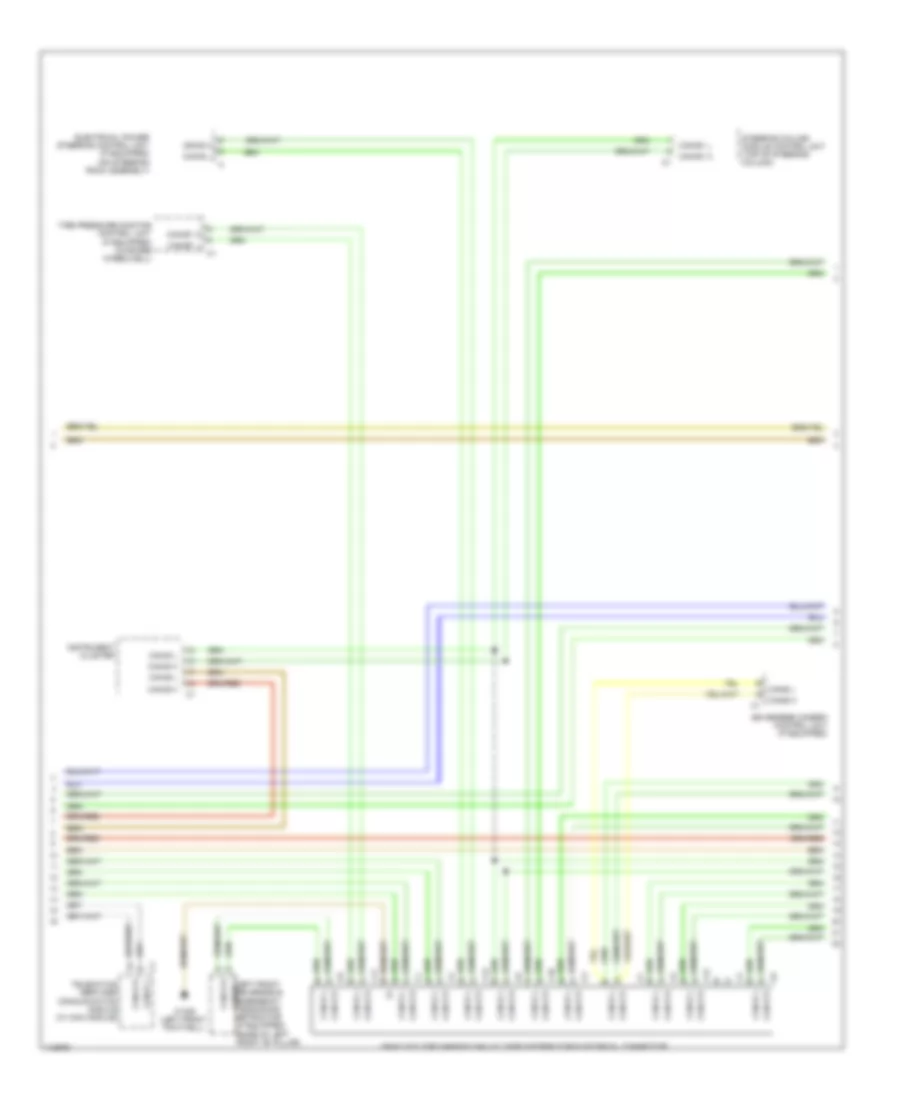
High/Low Bus Wiring Diagram, Sedan (1 of 5) for Mercedes-Benz E350 2013
List of elements for High/Low Bus Wiring Diagram, Sedan (1 of 5) for Mercedes-Benz E350 2013:
- 3.0l turbo diesel
- 3.5l & 4.6l twin turbo
- Audio/comand control panel
- Audio/comand display
- Can-a h
- Can-a l
- Can-c h
- Can-c l
- Can-g h
- Can-g l
- Comand control unit
- Drive train can voltage distributor electrical connector
- Dvd player (w/ rear entertainment (dvd))
- Electronic selector lever module control module (base of shift lever assembly)
- Electronic transmission control unit (under front of center console)
- Fuel pump control module (behind right quarterpanel)
- Fully integrated transmission control unit (in transmission)
- Intelligent servo module for direct select (if equipped) (bottom of transmission housing)
- Left front lamp unit
- Left rear display (w/ rear entertainment (dvd))
- Me-sfi (me) control module (except 3.0l turbo diesel) cdi control module (3.0l turbo diesel) (3.0l turbo diesel: in right front wheelwell) (3.5l: left side of engine) (4.6l: top center rear of engine)
- Module for direct select
- Navigation module
- Radio
- Right front lamp unit
- Right rear display (w/ rear entertainment (dvd))
- Telematics can voltage distributor electrical connector
- Transmission oil auxiliary pump control unit (bottom of transmission)
- Tv tuner (analog/digital) (right side of trunk)
- W/ audio 20
- W/ comand
- W/ direct select
- W/ electronic transmission control
- W/ intelligent servo
- W/ navigation
- W/o direct select
- W/o electronic transmission control
- W/o intelligent servo
- W15/1 (right front footwell)
- W15/5 (left front footwell)
- X138/1-c1
- X18/35-c1
- X22/2
- X55/3-c9
- X55/4-c9
High/Low Bus Wiring Diagram, Sedan (2 of 5) for Mercedes-Benz E350 2013
List of elements for High/Low Bus Wiring Diagram, Sedan (2 of 5) for Mercedes-Benz E350 2013:
- (left front footwell) w15/2
- C10
- C11
- C11c
- C12
- C13
- C18m
- C19i
- C20m
- C21m
- C22i
- C7i
- Can-a h
- Can-a l
- Can-b h
- Can-b l
- Can-e h
- Can-e l
- Can-g h
- Can-g l
- Comand control unit (if equipped)
- Driver seat control unit (under driver front seat)
- Dynamic multicontour seat pneumatic pump (if equipped) (left side of trunk)
- Electrical power steering control unit (if equipped)
- Front sam control module w/ fuse/ relay module (left rear of engine compt)
- Left front door control module
- Left front dynamic multicontour seat control unit (in left front seat back)
- Left rear bumper intelligent radar sensor (behind left side of rear bumper)
- Left rear door control module
- Left vehicle floor interior can voltage distributor electrical connector
- Overhead control panel control unit
- Panoramic sliding roof control module (integral to panoramic sliding roof drive unit)
- Radio (w/ audio 20 radio) radio w/ auto pilot system (w/ audio 50)
- Right rear bumper intelligent radar sensor (behind right side of rear bumper)
- Tailgate control unit (wagon) trunk lid control unit (sedan) (wagon: top of left "d" pillar) (sedan: center front of trunk)
- Trailer recognition control module (if equipped) (right side of trunk)
- W/ audio 20 radio & radio 50
- W/ panoramic sliding roof
- W/ partially electric driver seat adjustment
- W/ partially electric front passenger seat adjustment
- W/ partially electric seat adjustment
- W/o audio 20 radio & radio 50
- W/o panoramic sliding roof
- W/o partially electric seat adjustment
- Wagon
- X172/2
- X204
- X35/3-c1
- X55/3-c1
- X55/4-c1
- X8/45-c1
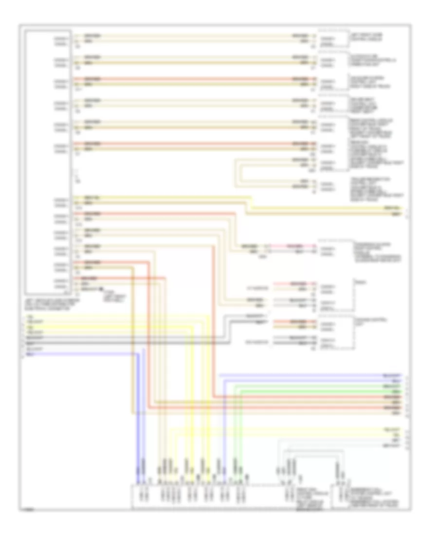
High/Low Bus Wiring Diagram, Sedan (3 of 5) for Mercedes-Benz E350 2013
List of elements for High/Low Bus Wiring Diagram, Sedan (3 of 5) for Mercedes-Benz E350 2013:
- C10
- C11
- C110
- C12
- C13
- C9i
- Can-b h
- Can-b l
- Can-e h
- Can-e l
- Front passenger seat control unit (under passenger front seat)
- Keyless go control unit (if equipped) (right side of trunk)
- Left front reversible emergency tensioning retractor (if equipped) (base of left "b" pillar)
- Me-sfi (me) control module (except 3.0l turbo diesel) cdi control module (3.0l turbo diesel) (3.0l turbo diesel: in right front wheelwell) (3.5l: left side of engine) (4.6l: top center rear of engine)
- Rear sam control module w/ fuse/relay module (except convertible: right side of trunk)
- Rear seat heaters control unit (if equipped) (right side of trunk)
- Right front door control module
- Right front dynamic multicontour seat control unit (in right front seat back)
- Right rear door control module
- Right vehicle floor interior can voltage distributor electrical connector
- Special purpose vehicle multi-function control unit (w/ taxi electrical system) (center front of trunk)
- Stationary heater unit (if equipped) (behind right side of front bumper)
- Tire pressure monitor control unit (if equipped) (in spare wheelwell)
- Vehicle floor chassis can voltage distributor electrical connector
- W/ fully electric seat adjustment w/ memory function
- W/ partially electric driver seat adjustment
- W/ partially electric front passenger seat adjustment
- W/o fully electric seat adjustment w/ memory function
- W15/2 (left front footwell)
- Weight sensing system control unit (wss) (if equipped) (under right front seat)
- X1/60-c1
- X35/4-c1
- X55/3
- X55/4-c1
- X55/4-c2
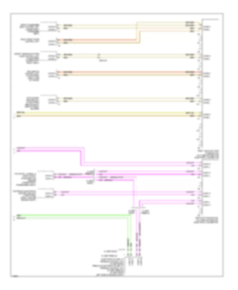
High/Low Bus Wiring Diagram, Sedan (4 of 5) for Mercedes-Benz E350 2013
List of elements for High/Low Bus Wiring Diagram, Sedan (4 of 5) for Mercedes-Benz E350 2013:
- (top center of front windshield)
- Airmatic control module (right front upper footwell)
- Automatic air conditioning control & operating unit (2 & 3 zones thermatic)
- Can-b h
- Can-b l
- Can-e h
- Can-e l
- Can-h h
- Can-h l
- Distronic electronic controller unit (w/ distronic plus) (front center engine compt)
- Early production
- Electronic ignition switch control unit
- Electronic stability program control unit (left side of engine compt)
- Instrument cluster
- Late production
- Multi-function camera (w/ active lane keeping assist, automatic lane detection traffic signal recogination & adaptive high beam assist)
- Night vision assist control unit (if equipped) (right kick panel)
- Parktronic control unit (if equipped) (right front footwell)
- Premium electronic stability program control unit (w/ esp premium)
- Radar sensor control unit (w/ distronic plus, blind spot assist & active lane keeping assist) (right front footwell)
- Rear axle electronic level control control unit (right front upper footwell)
- Right front reversible emergency tensioning retractor (if equipped) (base of right "b" pillar)
- Steering column module control unit (top of steering column)
- Steering wheel heater control unit (if equipped) (underside of steering column)
- Vehicle dynamics can voltage distributor electrical connector
- W/ esp basic
- W/ esp premium
- W/ hydraulics
- W/o hydraulics
- Yaw rate, lateral & longitudinal acceleration sensor (w/ esp premium) (under front passenger's seat)
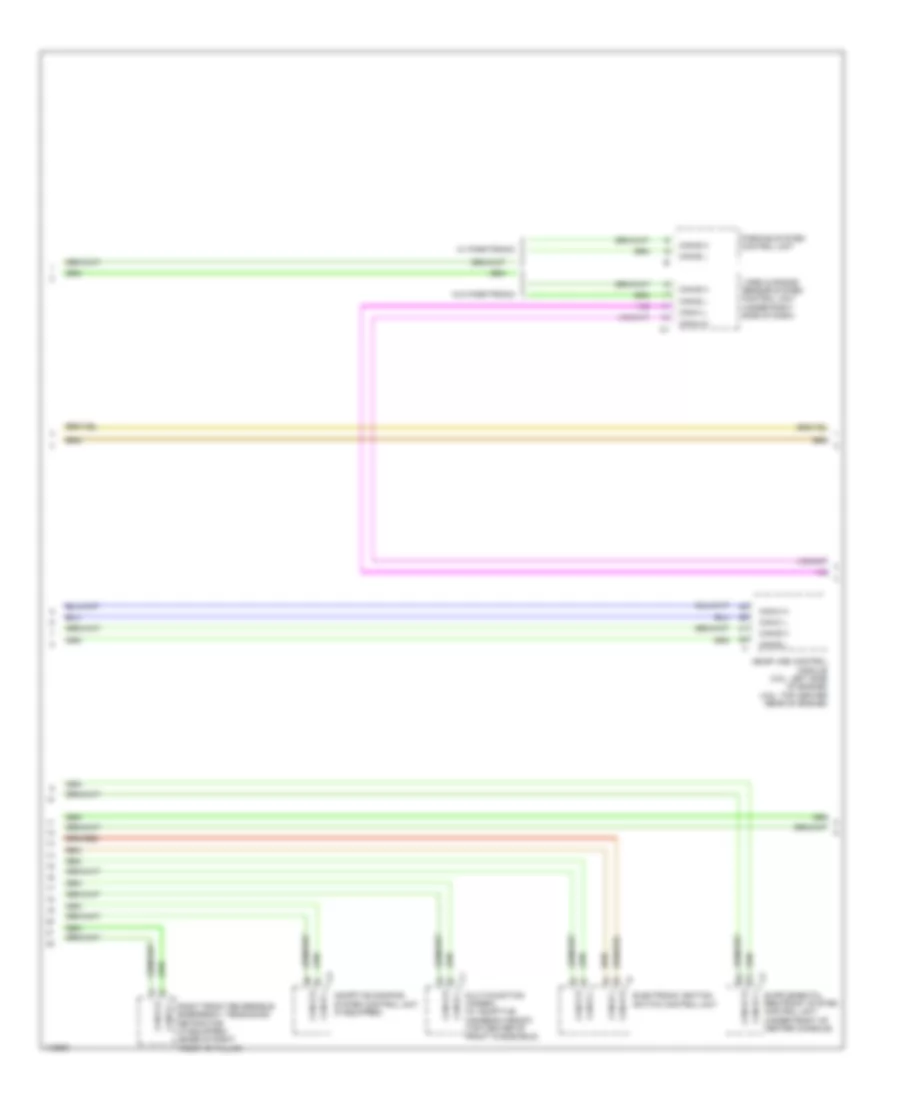
High/Low Bus Wiring Diagram, Sedan (5 of 5) for Mercedes-Benz E350 2013
List of elements for High/Low Bus Wiring Diagram, Sedan (5 of 5) for Mercedes-Benz E350 2013:
- 3.0l turbo diesel
- Battery management system control unit (on contactor assembly)
- Can-e h
- Can-e l
- Can-i h
- Can-i l
- Can-l h
- Can-l l
- Cdi control module (in right front wheelwell)
- Electric refrigerant compressor (lower left front of engine)
- Except 3.0l turbo diesel
- Hybrid can potential distributor electrical connector
- Left nox sensor control unit
- Me-sfi (me) control module (3.5l & 3.5l hybrid) (3.5l: left side of engine)
- Me-sfi (me) control module (3.5l: left side of engine) (4.6l: top center rear of engine)
- Nitrogen oxides control unit downstream of diesel particulate filter (3.0l turbo diesel) (under right front of vehicle)
- Nitrogen oxides control unit downstream of scr catalytic converter (near scr catalytic converter)
- Pnk
- Potential distributor electrical connector (can i)
- Power electronics control unit (bottom right side of engine)
- Right nox sensor control unit
- W15/1 (right front footwell)
- W18 (under driver's seat)
- X18/7
- X86/1-c1a
- X86/1-c2
- X86/3-c1
- X86/4-c1
High/Low Bus Wiring Diagram, Wagon (1 of 5) for Mercedes-Benz E350 2013
List of elements for High/Low Bus Wiring Diagram, Wagon (1 of 5) for Mercedes-Benz E350 2013:
- 3.0l turbo diesel
- 3.5l & 4.6l twin turbo
- Audio/comand control panel
- Audio/comand display
- Can-a h
- Can-a l
- Can-c h
- Can-c l
- Can-g h
- Can-g l
- Comand control unit
- Drive train can voltage distributor electrical connector
- Dvd player (w/ rear entertainment (dvd))
- Electronic selector lever module control module (base of shift lever assembly)
- Electronic transmission control unit (under front of center console)
- Fuel pump control module (behind right quarterpanel)
- Fully integrated transmission control unit (in transmission)
- Intelligent servo module for direct select (if equipped) (bottom of transmission housing)
- Left front lamp unit
- Left rear display (w/ rear entertainment (dvd))
- Me-sfi (me) control module (except 3.0l turbo diesel) cdi control module (3.0l turbo diesel) (3.0l turbo diesel: in right front wheelwell) (3.5l: left side of engine) (4.6l: top center rear of engine)
- Module for direct select
- Navigation module
- Radio
- Right front lamp unit
- Right rear display (w/ rear entertainment (dvd))
- Telematics can voltage distributor electrical connector
- Transmission oil auxiliary pump control unit (bottom of transmission)
- Tv tuner (analog/digital) (right side of trunk)
- W/ audio 20
- W/ comand
- W/ direct select
- W/ electronic transmission control
- W/ intelligent servo
- W/ navigation
- W/o direct select
- W/o electronic transmission control
- W/o intelligent servo
- W15/1 (right front footwell)
- W15/5 (left front footwell)
- X138/1-c1
- X18/35-c1
- X22/2
- X55/3-c9
- X55/4-c9
High/Low Bus Wiring Diagram, Wagon (2 of 5) for Mercedes-Benz E350 2013
List of elements for High/Low Bus Wiring Diagram, Wagon (2 of 5) for Mercedes-Benz E350 2013:
- (left front footwell) w15/2
- C10
- C11
- C11c
- C12
- C13
- C18m
- C19i
- C20m
- C21m
- C22i
- C7i
- Can-a h
- Can-a l
- Can-b h
- Can-b l
- Can-e h
- Can-e l
- Can-g h
- Can-g l
- Comand control unit (if equipped)
- Driver seat control unit (under driver front seat)
- Dynamic multicontour seat pneumatic pump (if equipped) (left side of trunk)
- Electrical power steering control unit (if equipped)
- Front sam control module w/ fuse/ relay module (left rear of engine compt)
- Left front door control module
- Left front dynamic multicontour seat control unit (in left front seat back)
- Left rear bumper intelligent radar sensor (behind left side of rear bumper)
- Left rear door control module
- Left vehicle floor interior can voltage distributor electrical connector
- Overhead control panel control unit
- Panoramic sliding roof control module (integral to panoramic sliding roof drive unit)
- Radio (w/ audio 20 radio) radio w/ auto pilot system (w/ audio 50)
- Right rear bumper intelligent radar sensor (behind right side of rear bumper)
- Tailgate control unit (wagon) trunk lid control unit (sedan) (wagon: top of left "d" pillar) (sedan: center front of trunk)
- Trailer recognition control module (if equipped) (right side of trunk)
- W/ audio 20 radio & radio 50
- W/ panoramic sliding roof
- W/ partially electric driver seat adjustment
- W/ partially electric front passenger seat adjustment
- W/ partially electric seat adjustment
- W/o audio 20 radio & radio 50
- W/o panoramic sliding roof
- W/o partially electric seat adjustment
- Wagon
- X172/2
- X204
- X35/3-c1
- X55/3-c1
- X55/4-c1
- X8/45-c1
High/Low Bus Wiring Diagram, Wagon (3 of 5) for Mercedes-Benz E350 2013
List of elements for High/Low Bus Wiring Diagram, Wagon (3 of 5) for Mercedes-Benz E350 2013:
- C10
- C11
- C110
- C12
- C13
- C9i
- Can-b h
- Can-b l
- Can-e h
- Can-e l
- Front passenger seat control unit (under passenger front seat)
- Keyless go control unit (if equipped) (right side of trunk)
- Left front reversible emergency tensioning retractor (if equipped) (base of left "b" pillar)
- Me-sfi (me) control module (except 3.0l turbo diesel) cdi control module (3.0l turbo diesel) (3.0l turbo diesel: in right front wheelwell) (3.5l: left side of engine) (4.6l: top center rear of engine)
- Rear sam control module w/ fuse/relay module (except convertible: right side of trunk)
- Rear seat heaters control unit (if equipped) (right side of trunk)
- Right front door control module
- Right front dynamic multicontour seat control unit (in right front seat back)
- Right rear door control module
- Right vehicle floor interior can voltage distributor electrical connector
- Special purpose vehicle multi-function control unit (w/ taxi electrical system) (center front of trunk)
- Stationary heater unit (if equipped) (behind right side of front bumper)
- Tire pressure monitor control unit (if equipped) (in spare wheelwell)
- Vehicle floor chassis can voltage distributor electrical connector
- W/ fully electric seat adjustment w/ memory function
- W/ partially electric driver seat adjustment
- W/ partially electric front passenger seat adjustment
- W/o fully electric seat adjustment w/ memory function
- W15/2 (left front footwell)
- Weight sensing system control unit (wss) (if equipped) (under right front seat)
- X1/60-c1
- X35/4-c1
- X55/3
- X55/4-c1
- X55/4-c2
High/Low Bus Wiring Diagram, Wagon (4 of 5) for Mercedes-Benz E350 2013
List of elements for High/Low Bus Wiring Diagram, Wagon (4 of 5) for Mercedes-Benz E350 2013:
- (top center of front windshield)
- Airmatic control module (right front upper footwell)
- Automatic air conditioning control & operating unit (2 & 3 zones thermatic)
- Can-b h
- Can-b l
- Can-e h
- Can-e l
- Can-h h
- Can-h l
- Distronic electronic controller unit (w/ distronic plus) (front center engine compt)
- Early production
- Electronic ignition switch control unit
- Electronic stability program control unit (left side of engine compt)
- Instrument cluster
- Late production
- Multi-function camera (w/ active lane keeping assist, automatic lane detection traffic signal recogination & adaptive high beam assist)
- Night vision assist control unit (if equipped) (right kick panel)
- Parktronic control unit (if equipped) (right front footwell)
- Premium electronic stability program control unit (w/ esp premium)
- Radar sensor control unit (w/ distronic plus, blind spot assist & active lane keeping assist) (right front footwell)
- Rear axle electronic level control control unit (right front upper footwell)
- Right front reversible emergency tensioning retractor (if equipped) (base of right "b" pillar)
- Steering column module control unit (top of steering column)
- Steering wheel heater control unit (if equipped) (underside of steering column)
- Vehicle dynamics can voltage distributor electrical connector
- W/ esp basic
- W/ esp premium
- W/ hydraulics
- W/o hydraulics
- Yaw rate, lateral & longitudinal acceleration sensor (w/ esp premium) (under front passenger's seat)
High/Low Bus Wiring Diagram, Wagon (5 of 5) for Mercedes-Benz E350 2013
List of elements for High/Low Bus Wiring Diagram, Wagon (5 of 5) for Mercedes-Benz E350 2013:
- 3.0l turbo diesel
- Battery management system control unit (on contactor assembly)
- Can-e h
- Can-e l
- Can-i h
- Can-i l
- Can-l h
- Can-l l
- Cdi control module (in right front wheelwell)
- Electric refrigerant compressor (lower left front of engine)
- Except 3.0l turbo diesel
- Hybrid can potential distributor electrical connector
- Left nox sensor control unit
- Me-sfi (me) control module (3.5l & 3.5l hybrid) (3.5l: left side of engine)
- Me-sfi (me) control module (3.5l: left side of engine) (4.6l: top center rear of engine)
- Nitrogen oxides control unit downstream of diesel particulate filter (3.0l turbo diesel) (under right front of vehicle)
- Nitrogen oxides control unit downstream of scr catalytic converter (near scr catalytic converter)
- Pnk
- Potential distributor electrical connector (can i)
- Power electronics control unit (bottom right side of engine)
- Right nox sensor control unit
- W15/1 (right front footwell)
- W18 (under driver's seat)
- X18/7
- X86/1-c1a
- X86/1-c2
- X86/3-c1
- X86/4-c1