COMPUTER DATA LINES
Computer Data Lines Wiring Diagram for Isuzu Rodeo S 2004
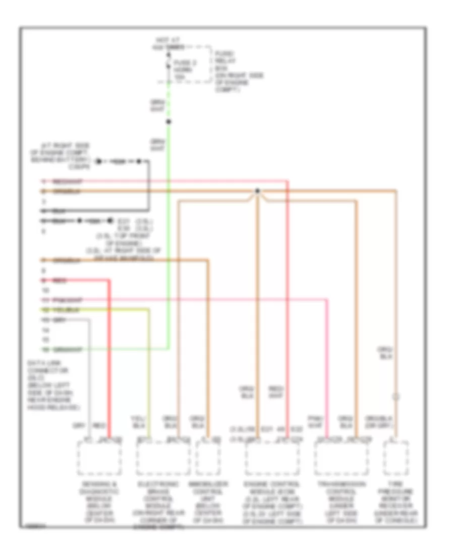
List of elements for Computer Data Lines Wiring Diagram for Isuzu Rodeo S 2004:
- (3.2l)
- (3.5l)
- (3.5l) (3.2l)
- (at right side of engine compt, behind battery) c36/p6
- C4 b6
- C74
- C78
- C79
- Data link connector (dlc) (below left side of dash, near engine hood release)
- E21
- E21 e30 (3.5l: top front of engine) (3.2l: at right side of intake manifold)
- E22
- Electronic brake control module (on right rear corner of engine compt)
- Engine control module (ecm) (3.2l: left rear of engine compt) (3.5l di: left side of engine compt)
- Fuse 2 horn 10a
- Fuse/ relay box (on right side of engine compt)
- Hot at all times
- I30
- I55
- Immobilizer control unit (below center of dash)
- Red
- Sensing & diagnostic module (below center of dash)
- Tire pressure monitor receiver (under rear of console)
- Transmission control module (under left side of dash)
 Русский