ANTI-THEFT
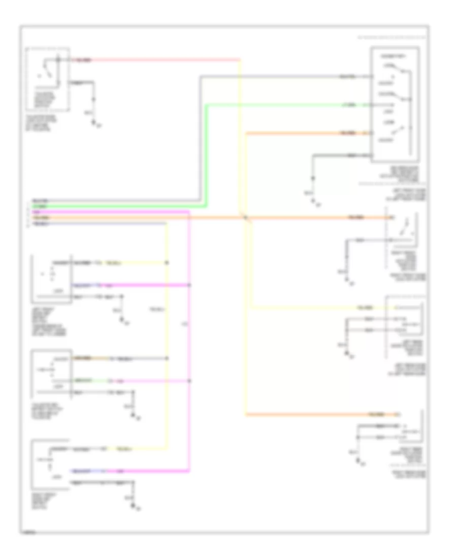
Forced Entry Wiring Diagram (1 of 2) for Isuzu Rodeo S 2004

List of elements for Forced Entry Wiring Diagram (1 of 2) for Isuzu Rodeo S 2004:
- Act pos locked
- Act pos unlocked
- Anti- theft fuse 23 10a
- Anti-theft horn (on right rear corner of engine compartment)
- Anti-theft indicator light
- Battery input
- C36/p6 (at right side of engine compt, behind battery)
- Dash fuse box (behind left side of dash, behind panel)
- Diode box 5
- Disarm lock input
- Disarm unlock input
- Door locks system
- Door/hatch open in
- Dr door act ctrl
- Engine hood input
- Engine hood switch (at right rear corner of engine compt)
- Exterior lights system
- Fuse/relay box (on right side of engine compartment)
- Ground
- Hatch gate open switch (inside top center of tailgate, on latch assembly)
- Headlight rly ctrl
- Headlights system
- Horn fuse 2 10a
- Hot at all times
- Hot in acc or on
- Ignition input
- Ignition switch
- Interior lights system
- J/c b
- Key in ignition
- Key reminder switch
- Key rod act posit
- Keyless entry & anti-theft control unit (behind right side of dash, above kick panel)
- Left front door switch
- Left rear door switch
- Lock input
- Lock/unlock input
- Power door lock fuse 7 20a
- Red
- Right front door switch
- Right rear door switch
- Security horn ctrl
- Security ind ctrl
- Switch unit a
- Taillight relay
- Unlock input
- Warning system
- Wiper/ washer system
Forced Entry Wiring Diagram (2 of 2) for Isuzu Rodeo S 2004
List of elements for Forced Entry Wiring Diagram (2 of 2) for Isuzu Rodeo S 2004:
- (momentary)
- Driver's door key detect & actuator position switches
- Left front door key detect switch (inside rear of left front door, on key cylinder)
- Left front door lock actuator (in left front door)
- Left rear door actuator position switch
- Left rear door lock actuator (in left rear door)
- Lock
- Right front door actuator position switch
- Right front door key detect switch
- Right front door lock actuator
- Right rear door actuator position switch
- Right rear door lock actuator
- Tailgate actuator position switch
- Tailgate door lock actuator (at center of tailgate)
- Tailgate key detect switch (in center of tailgate)
- Unlock
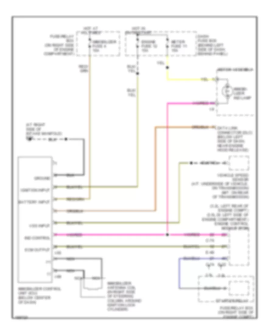
Immobilizer Wiring Diagram for Isuzu Rodeo S 2004
List of elements for Immobilizer Wiring Diagram for Isuzu Rodeo S 2004:
- (+)
- (-)
- (3.2l: left rear of engine compt) (3.5l di: left side of engine compartment) engine control module (ecm)
- (at right side of intake manifold) e30
- 3.2l
- 3.5l
- Battery input
- C-74
- Dash fuse box (behind left side of dash, behind panel)
- Data link connector (dlc) (below left side of dash, near engine hood release)
- E-22
- E-48
- Ecm output
- Engine fuse 12 15a
- Fuse/relay box (on right side of engine compartment)
- Fuse/relay box (on right side of engine compt)
- Ground
- Hot at all times
- Hot in on or start
- I-55
- I-9
- I-99
- Ignition input
- Immobi- lizer ind lamp
- Immobilizer antenna coil (in right side of steering column, around ignition lock cylinder)
- Immobilizer control unit (icu) (below center of dash)
- Immobilizer fuse 4 10a
- Ind control
- Meter assembly
- Meter fuse 11 15a
- Nca
- Starter relay
- Vehicle speed sensor (a/t: underside of vehicle, on transmission) (m/t: on rear of transmission)
- Vss input