ENGINE PERFORMANCE
3.2L
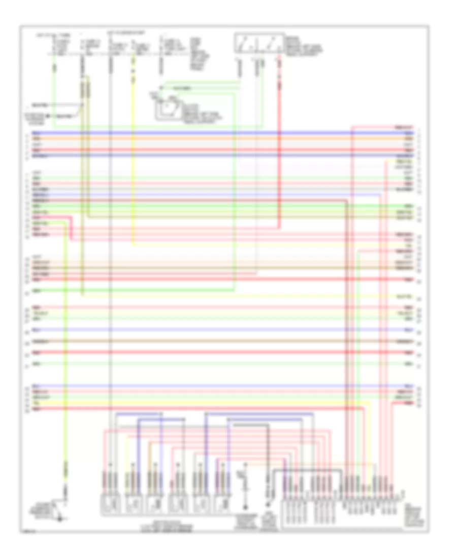
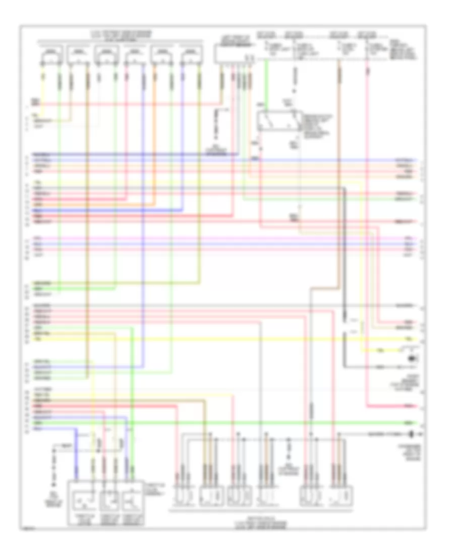
3.2L, Engine Performance Wiring Diagram (1 of 4) for Isuzu Rodeo S 2004

List of elements for 3.2L, Engine Performance Wiring Diagram (1 of 4) for Isuzu Rodeo S 2004:
- (at left rear corner of engine compt, on inner fender panel) c16
- (at left side of intake manifold)
- (at right side of intake manifold) e30
- (m/t)
- 2 fuel inj
- 3 fuel inj
- 4 fuel inj
- 5 inj ctrl
- A/c clutch
- A/c req
- Air conditioning system
- Ap sen1 gnd
- Ap sen2 gnd
- B1s1
- B1s2
- B2s1
- B2s2
- Brake sw in
- C.q. sign in
- Ckp in
- Clutch sw in
- Crankshaft position (ckp) sensor (on lower right side of engine)
- Cruise brake
- Cruise control system
- E-21
- E28
- E28 (at left side of intake manifold)
- E30 (at right side of intake manifold)
- Ecm main relay
- Ect in
- Engine control module (left rear of engine compt)
- Engine coolant temperature (ect) sensor (on right front of engine)
- Etc gnd
- Fuel injectors (1,3,5: right side of engine) (2,4,6: left side of engine)
- Fuel pump
- Fuel pump fuse 12 20a
- Fuel pump relay
- Fuel tank unit
- Fuse 13 ecm 10a
- Fuse 15 ign b1 60a
- Fuse ecm 30a
- Fuse/ relay box (on right side of engine compt)
- Gnd
- Headlights system
- Ho2s b1s2 -
- Ho2s2 h gnd
- Hot at all times
- Iat in
- Ig coil2 ctrl
- Ig coil3 ctrl
- Ign feed
- Ind ctrl
- J/c b
- Knock sig in
- Lights on
- Maf in
- Map in
- N01 fuel inj
- O2 sens heater fuse 11 20a
- Pins not used: 8-12, 35-36
- Pnk
- Psp sw in
- Red
- Ref volt
- Res/acc in
- Serial data
- Starter feed
- Starting/charging system
- Tach
- Throttle position sensor 1
- Throttle position sensor 2
- Throttle val
- Throttle valve assembly
- Throttle valve motor
- Tps1 gnd
- Tps2 gnd
- Tps2 sign
- Vapor sen
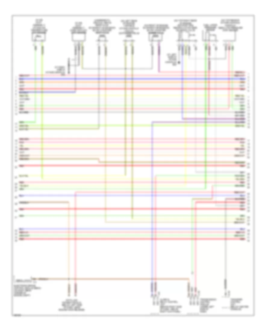
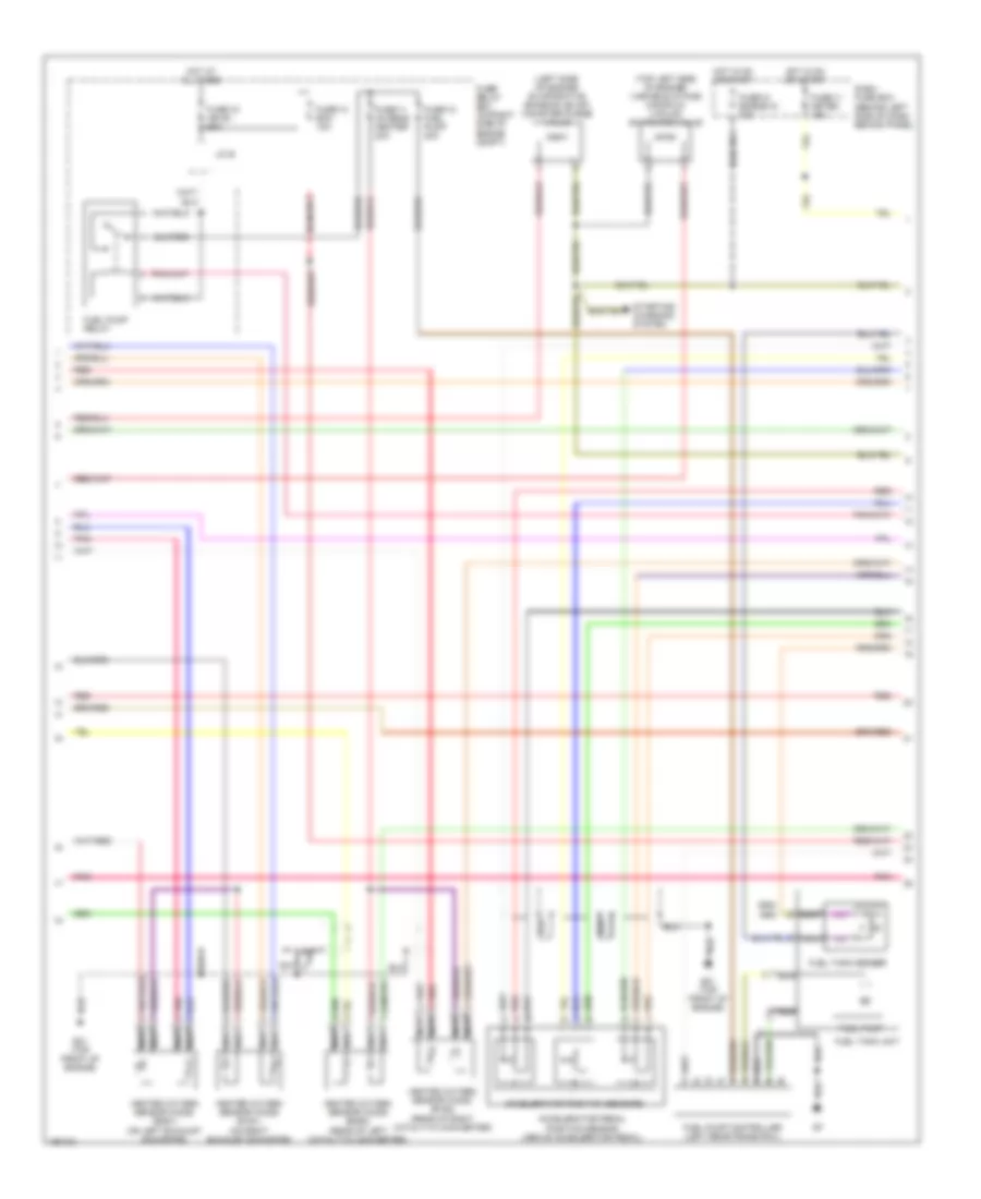
3.2L, Engine Performance Wiring Diagram (2 of 4) for Isuzu Rodeo S 2004
List of elements for 3.2L, Engine Performance Wiring Diagram (2 of 4) for Isuzu Rodeo S 2004:
- 1,3,5 coil in
- 2,4,6 coil in
- Brake switch (behind left side of dash, on brake pedal support)
- Clutch switch (behind left side of dash, on clutch pedal support)
- Coil 1 ctrl
- Coil 2 ctrl
- Coil 3 ctrl
- Coil 4 ctrl
- Coil 5 ctrl
- Coil 6 ctrl
- Condenser (0n right front of condenser)
- Dash fuse box (behind left side of dash, behind panel)
- E-16
- E-17
- E-18
- E29 (at left side of intake manifold)
- Est 11
- Est 12
- Est 13
- Est 21
- Est 22
- Est 23
- Fuse 11 meter 15a
- Fuse 12 engine ig 15a
- Fuse 13 ig coil 15a
- Fuse 14 back up/ turn light 15a
- Fuse 6 stop light 15a
- Gnd
- Hot at all times
- Hot in on or start
- Ign
- Ignition coils (1,3,5: right side of engine) (2,4,6: left side of engine)
- Ion sensing module (on top of intake manifold)
- Ioncq1
- Ionk1
- Pnk
- Power steering pressure switch
- Red
- Starting/ charging system
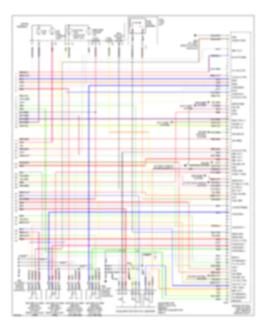
3.2L, Engine Performance Wiring Diagram (3 of 4) for Isuzu Rodeo S 2004
List of elements for 3.2L, Engine Performance Wiring Diagram (3 of 4) for Isuzu Rodeo S 2004:
- (at left side of intake manifold) e28
- (in air duct assembly) intake air temperature (iat) sensor
- (in air duct assembly) mass air flow (maf) sensor
- (on front of engine) evaporative emission (evap) canister purge valve
- (on left rear of engine) variable intake manifold vacuum switching valve
- (on top rear of intake manifold) manifold absolute pressure (map) sensor
- (on top right rear of engine) exhaust gas recirculation (egr) solenoid valve
- (underneath vehicle, above rear axle) evaporative emission (evap) canister vent valve
- Alarm & relay control unit (behind right side of dash, above right kick panel)
- B-19
- C-4
- C-78
- Data link connector (dlc) (below left side of dash, near engine hood release)
- Electronic brake control module (ebcm) (on right rear corner of engine compt)
- Est 11
- Est 12
- Est 13
- Fuel vapor pressure sensor
- I-42
- Pnk
- Red
- Serial data
- Transfer control unit (below center console)
- Transmission control module (under left side of dash)
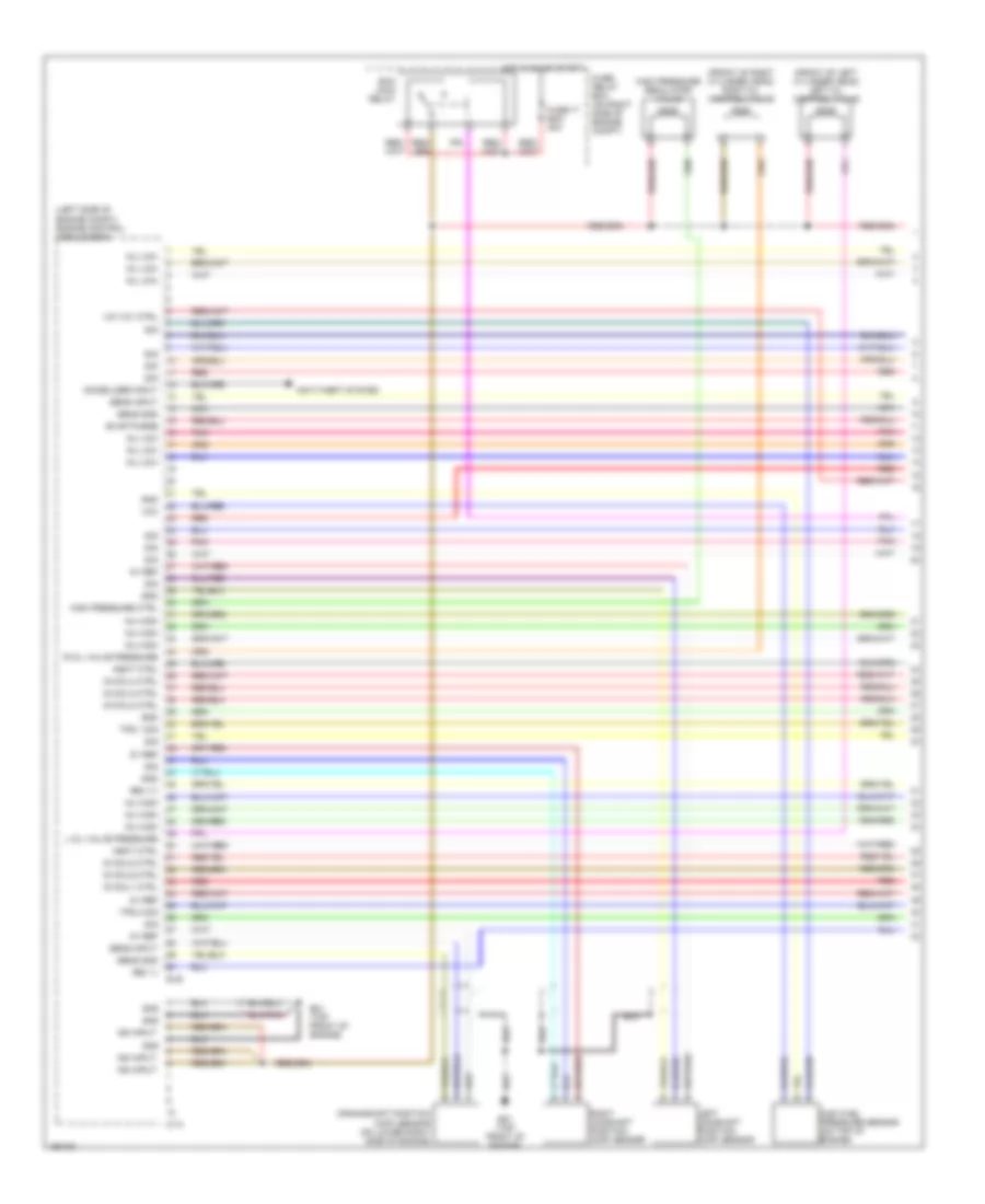
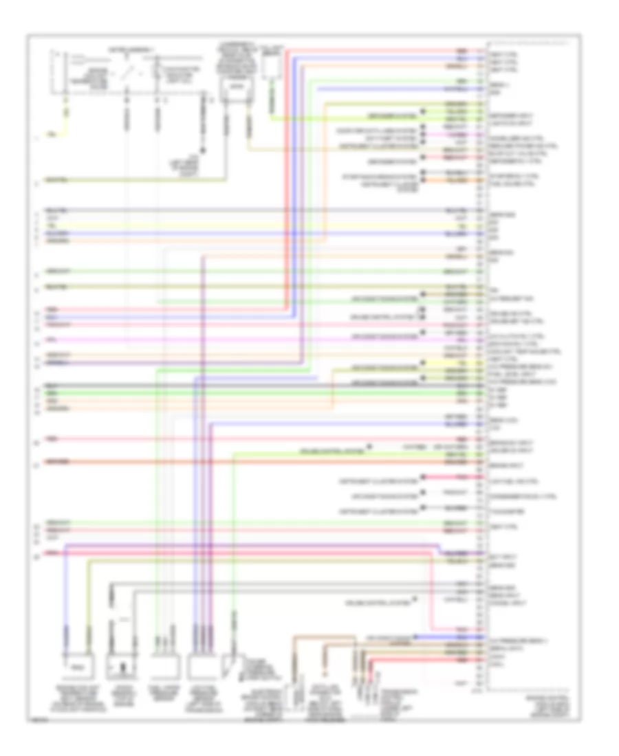
3.2L, Engine Performance Wiring Diagram (4 of 4) for Isuzu Rodeo S 2004
List of elements for 3.2L, Engine Performance Wiring Diagram (4 of 4) for Isuzu Rodeo S 2004:
- "u/s" ind
- (at right side of intake manifold)
- 6 fuel inj
- Accelerator pedal position sensor (above accelerator pedal)
- Accelerator positioin sensors
- Anti-theft system
- Ap sensor 1
- Ap sensor 2
- Ap sensor 3
- Aps3 gnd
- B1s1
- B1s2
- B2s1
- B2s2
- Can +
- Can cut val
- Can-
- Cruise control system
- Cruise lmp
- Cruise sw
- Defog req
- Defog rly
- Defogger system
- Defogger sysyem
- Dlc
- E-22
- E28 (at left side of intake manifold)
- E30
- E30 (at right side of intake manifold)
- Ect out
- Egr ctrl hi
- Egr in
- Eng coolant temp gauge
- Engine control module (ecm) (left rear of engine compt)
- Evap purge
- F-1
- Fuel gauge
- Fuel sen
- Fuel tank sender
- Fuel tank unit
- Gnd
- Ground
- Heated oxygen sensor (ho2s) (b1s1) (in right front exhaust pipe)
- Heated oxygen sensor (ho2s) (b1s2) (rear of right catalytic converter)
- Heated oxygen sensor (ho2s) (b2s1) (in left front exhaust pipe)
- Heated oxygen sensor (ho2s) (b2s2) (rear of left catalytic converter)
- Ho2s b1s1 +
- Ho2s b1s1 -
- Ho2s b1s2 +
- Ho2s b2s1 +
- Ho2s b2s1 -
- Ho2s b2s2 +
- Ho2s b2s2 -
- Ho2s1 h gnd
- Ho2s1h gnd
- I-1
- I-2
- I-9
- Ig coil1 ctrl
- Ig coil4 ctrl
- Ig coil5 ctrl
- Ig coil6 ctrl
- Ign feed
- Imm ind
- Immobil in
- Low fuel warning light
- Malfunc- tion indicator light (mil)
- Meter assembly
- Mil ind ctrl
- Nca
- Pnk
- Red
- Reduced power ind
- Ref volt
- Sens gnd
- St relay ctrl
- Starting/charging system
- Tach- ometer
- Th val mtr
- Tps 1 sign
- Up ind in
- Vapor press
- Vim vsv ctrl
3.5L
3.5L, Engine Performance Wiring Diagram (1 of 4) for Isuzu Rodeo S 2004
List of elements for 3.5L, Engine Performance Wiring Diagram (1 of 4) for Isuzu Rodeo S 2004:
- (front of left cylinder head) left oil control valve
- (front of right cylinder head) right oil control valve
- (left side of engine compt) engine control module (ecm)
- 5v ref
- Anti-theft system
- C-74
- Crankshaft position (ckp) sensor (on lower right side of engine)
- E-48
- E21 (top front of engine)
- Ecm main relay
- Evap purge
- Fuse-17 ecm 30a
- Fuse/ relay box (on right side of engine compt)
- Gnd
- Heat ctrl
- High fuel pressure sensor (on top of engine)
- High pressure ctrl
- High pressure regulator valve
- Hot in on or start
- Ig coil1 ctrl
- Ig coil2 ctrl
- Ig coil3 ctrl
- Ig coil4 ctrl
- Ig coil5 ctrl
- Ig coil6 ctrl
- Ign input
- Immobilizer input
- Inj high
- Inj low
- L oil valve pressure
- Left camshaft position (cmp) sensor
- Nca
- Pnk
- R oil valve pressure
- Red
- Rev (+)
- Rev (-)
- Right camshaft position (cmp) sensor
- Sens gnd
- Sens input
- Sig
- Tps 1 sig
- Tps 2 sig
- Vcc
- Vim vcv ctrl
3.5L, Engine Performance Wiring Diagram (2 of 4) for Isuzu Rodeo S 2004
List of elements for 3.5L, Engine Performance Wiring Diagram (2 of 4) for Isuzu Rodeo S 2004:
- (1,3,5: top right side of engine) (2,4,6: top left side of engine) fuel injectors
- (left front of engine compt) maf/iat sensor
- Brake switch (behind left side of dash, on brake pedal support)
- Condenser (on top front of engine)
- Dash fuse box (behind left side of dash, behind panel)
- E21 (top front of engine)
- E23 (top front of engine)
- Fuse-13 ig coil 15a
- Fuse-14 back-up/ turn light 15a
- Fuse-3 starter 10a
- Fuse-6 stop light 15a
- Hot in on or start
- Iat
- Ignition coils (1,3,5: right side of engine) (2,4,6: left side of engine)
- Knock sensor 1 (top of engine)
- Nca
- Pnk
- Red
- Throttle position sensor 1
- Throttle position sensor 2
- Throttle valve assembly
- Throttle valve motor
3.5L, Engine Performance Wiring Diagram (3 of 4) for Isuzu Rodeo S 2004
List of elements for 3.5L, Engine Performance Wiring Diagram (3 of 4) for Isuzu Rodeo S 2004:
- (left side of engine) evaporative emission (evap) canister purge valve
- (top left side of engine) variable intake manifold vacuum switching valve
- Accelerator pedal position sensor (above accelerator pedal)
- Accelerator position sensors
- Dash fuse box (behind left side of dash, behind panel)
- E21 (top front of engine)
- Fuel pump
- Fuel pump controller (left rear frame rail)
- Fuel pump relay
- Fuel tank sender
- Fuel tank unit
- Fuse-11 meter 15a
- Fuse-11 o2 sens, heater 20a
- Fuse-12 engine ig 15a
- Fuse-12 fuel pump 20a
- Fuse-13 ecm 10a
- Fuse-15 ign b1 60a
- Fuse/ relay box (on right side of engine compt)
- Heated oxygen sensor (ho2s) (b1s1) (on right exhaust downpipe)
- Heated oxygen sensor (ho2s) (b1s2) (rear of right catalytic converter)
- Heated oxygen sensor (ho2s) (b2s1) (on left exhaust downpipe)
- Heated oxygen sensor (ho2s) (b2s2) (rear of left catalytic converter)
- Hot at all times
- Hot in on or start
- J/c b
- Nca
- Pnk
- Red
- Starting/ charging system
3.5L, Engine Performance Wiring Diagram (4 of 4) for Isuzu Rodeo S 2004
List of elements for 3.5L, Engine Performance Wiring Diagram (4 of 4) for Isuzu Rodeo S 2004:
- (underneath vehicle, above rear axle) evaporative emission (evap) canister vent valve
- 5v ref
- A/c clutch rly ctrl
- A/c pressure sens (-)
- A/c pressure sens (5v)
- A/c pressure sens (vcc)
- A/c request sig
- Air conditioning system
- Anti-theft system
- B6 serial data
- Brake input
- Brake sw input
- C-4
- C-74
- C-78
- C16 (left rear of engine compt)
- Can-h
- Can-l
- Cancel input
- Canl-h
- Canl-l
- Computer data lines system
- Condenser fan rly ctrl
- Coolant temp gauge ctrl
- Cruise control system
- Cruise ind ctrl
- Cruise on input
- Cruise set ind ctrl
- Data link connector (dlc) (below left side of dash, near engine hood release)
- Defogger input
- Defogger rly ctrl
- Defogger system
- Ecm main rly ctrl
- Ect input
- Electronic brake control module (ebcm) (on right rear corner of engine compt)
- Engine control module (ecm) (left side of engine compt)
- Engine coolant temperature (ect) sensor (on rear of engine, in coolant manifold)
- Engine coolant temperature gauge
- Evap cut valve ctrl
- Fuel gauge ctrl
- Fuel level input
- Fuel vapor pressure sensor
- Gnd
- Heat ctrl
- I-1
- I-2
- Ign
- Immobilizer ind ctrl
- Instrument cluster system
- J1850
- Knock sensor 2 (top of engine)
- Lights on input
- Low fuel ind ctrl
- Low fuel pressure sensor (left side of transmission)
- Malfunction indicator light (mil)
- Meter assembly
- Nca
- Pnk
- Power steering pressure (psp) switch
- Red
- Reduced power ind ctrl
- Sens (-)
- Sens (vcc)
- Sens gnd
- Sens input
- Sens sig
- Serial data
- Sig
- Starter rly ctrl
- Starting/charging system
- Tachometer
- Taillight relay
- Transmission control module (under left side of dash)
- Vcc