CRUISE CONTROL
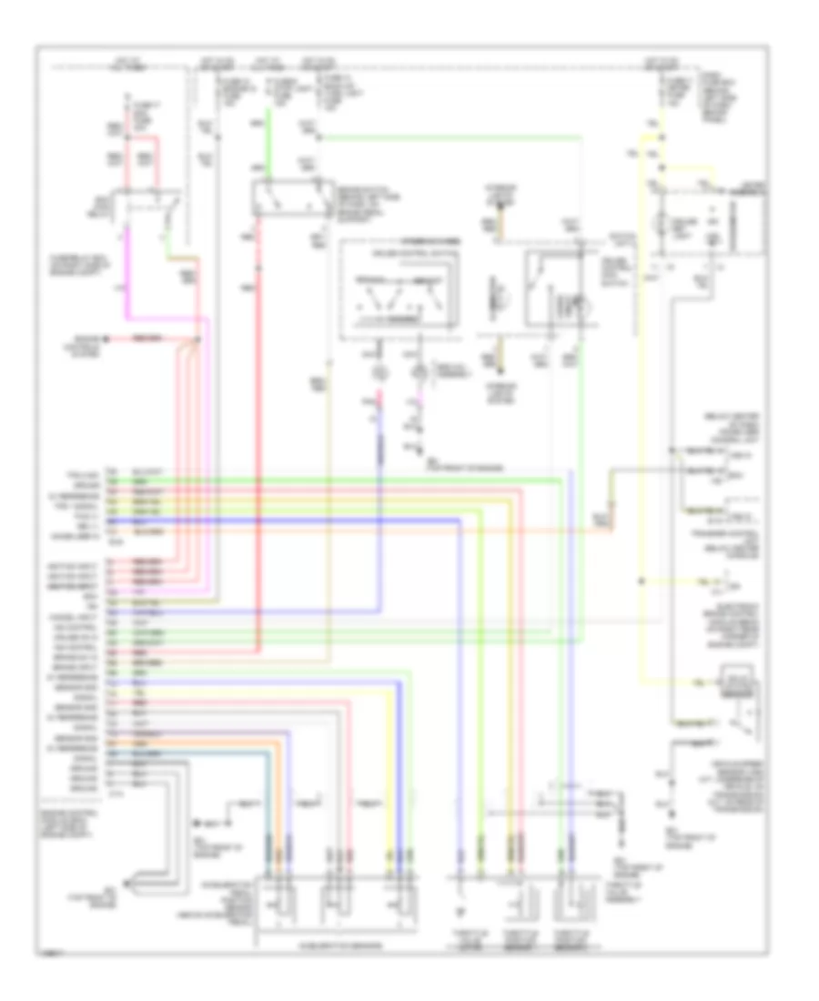
3.2L
3.2L, Cruise Control Wiring Diagram for Isuzu Rodeo S 2004

List of elements for 3.2L, Cruise Control Wiring Diagram for Isuzu Rodeo S 2004:
- (below center of dash) immobilizer control unit
- Acceleration position sensor assembly
- Acceleration sensors
- Ap sen1 gnd
- Ap sen2 gnd
- Ap sensor 1
- Ap sensor 2
- Ap sensor 3
- Aps3 gnd
- B-19
- Brake sw in
- Brake switch (behind left side of dash, on brake pedal support)
- C-4
- C16 (at left rear corner of engine compt, on inner fender panel)
- Cancel
- Cancel in
- Cb-11 meter fuse 15a
- Cb-12 engine ig fuse 15a
- Cb-14 back-up/ turn light fuse 15a
- Cb-6 stop light fuse 15a
- Clutch switch (m/t) (behind left side of dash, on clutch pedal support)
- Cruise brake
- Cruise control main switch
- Cruise control switch
- Cruise lmp
- Cruise set light
- Cruise sw
- Dash fuse box (behind left side of dash, behind panel)
- Drive input
- E-21
- E-22
- E28 (at left side of intake manifold)
- E30 (at right side of intake manifold)
- Eb-17 ecm fuse 30a
- Ecm main relay
- Electronic brake control module (ebcm) (on right rear corner of engine compartment)
- Engine control module (ecm) (left rear of engine compt)
- Engine controls system
- Fuse/relay box (on right side of engine compt)
- Gnd
- Hot at all times
- Hot in on or start
- I-2
- I-55
- I-9
- Ign
- Ign feed
- Illumination
- Ind on/off cruise
- Interior lights system
- Meter assembly
- Nca
- On switch
- Pnk
- Red
- Ref volt
- Res/acc
- Set/cst
- Solid state sensor
- Speedometer
- Srs coil assembly
- Steering wheel
- Switch unit a
- Th val mtr+
- Throttle position sensor 1
- Throttle position sensor 2
- Throttle val-
- Throttle valve assembly
- Throttle valve motor
- Tps 1 sign
- Tps1 gnd
- Tps2 gnd
- Tps2 sign
- Transfer control unit (below center console)
- Vehicle speed sensor (underside of vehicle, on transmission)
- Vss in
3.5L
3.5L, Cruise Control Wiring Diagram for Isuzu Rodeo S 2004
List of elements for 3.5L, Cruise Control Wiring Diagram for Isuzu Rodeo S 2004:
- (below center of dash) immobilizer control unit
- (top front of engine)
- 5v reference
- Acceleration pedal position sensor (above accelerator pedal)
- Acceleration sensors
- B-19
- Brake input
- Brake sw in
- Brake switch (behind left side of dash, on brake pedal support)
- C-4
- C-74
- Cancel
- Cancel input
- Cruise control main switch
- Cruise control switch
- Cruise on in
- Cruise set light
- Dash fuse box (behind left side of dash, behind panel)
- E-48
- E21
- E21 (top front of engine)
- Ecm
- Ecm main relay
- Electronic brake control module (ebcm) (on right rear corner of engine compt)
- Engine control module (ecm) (left side of engine compt)
- Engine controls system
- Fuse-11 meter fuse 15a
- Fuse-12 engine ig fuse 15a
- Fuse-14 back-up/ turn light fuse 15a
- Fuse-17 ecm fuse 30a
- Fuse-6 stop light fuse 15a
- Fuse/relay box (on right side of engine compt)
- Fwd (+)
- Ground
- Hot at all times
- Hot in on or start
- I-2
- I-55
- I-9
- Ign
- Ignition input
- Ignition input ignition input
- Illumination
- Immobilizer in
- Ind control
- Ind on/off cruise
- Interior lights system
- Meter assembly
- Nca
- Pnk
- Red
- Res/acc
- Rev (-)
- Sensor gnd
- Set/cst
- Signal
- Solid state sensor
- Speedometer
- Srs coil assembly
- Steering wheel
- Switch unit a
- Throttle position sensor 1
- Throttle position sensor 2
- Throttle valve assembly
- Throttle valve motor
- Tps 1 signal
- Tps 2 sig
- Transfer control unit (below center console)
- Vehicle speed sensor (vss) (a/t: underside of vehicle, on transmission) (m/t: on rear of transmission)
- Vss in