CRUISE CONTROL
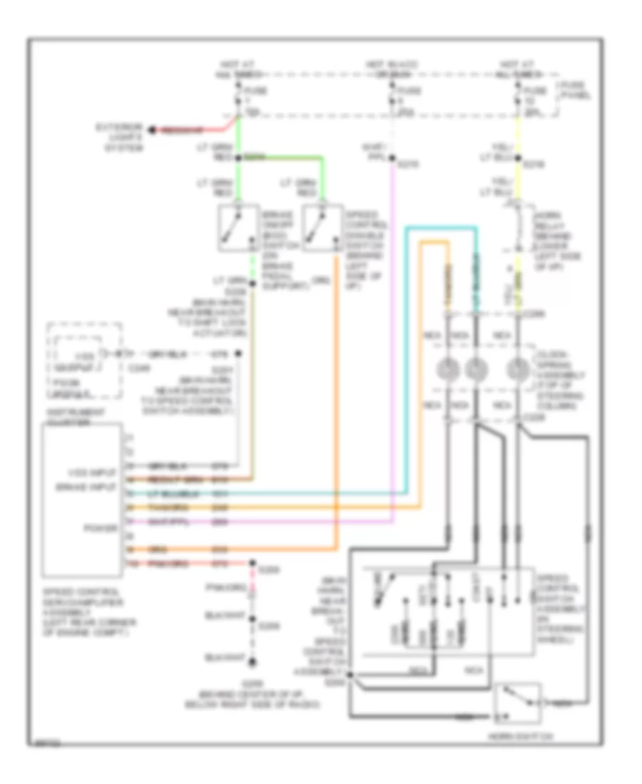
Cruise Control Wiring Diagram for Ford Aerostar 1997
List of elements for Cruise Control Wiring Diagram for Ford Aerostar 1997:
- (main harn, near break- out to speed control switch assembly) s200
- Brake input
- Brake on/off (boo) switch (on brake pedal support)
- C228
- C249
- Clock- spring assembly (top of steering column)
- Coast
- Exterior lights system
- Fuse 15a
- Fuse 20a
- Fuse 30a
- Fuse panel
- G206 (behind center of i/p, below right side of radio)
- Horn relay (behind lower left side of i/p)
- Horn switch
- Hot at all times
- Hot in acc or run
- Instrument cluster
- Nca
- Off
- Ohms
- Power
- Psom module
- Resume
- S200
- S201 (main harn, near breakout to speed control switch assembly)
- S209
- S214
- S215
- S218
- S228 (main harn, near breakout to shift lock actuator)
- Set/ accel
- Speed control disable switch (behind left side of i/p)
- Speed control servo/amplifier assembly (left rear corner of engine compt)
- Speed control switch assembly (in steering wheel)
- Vss input
- Vss output
 English