ANTI-LOCK BRAKES
Anti-lock Brake Wiring Diagrams for Ford Aerostar 1997
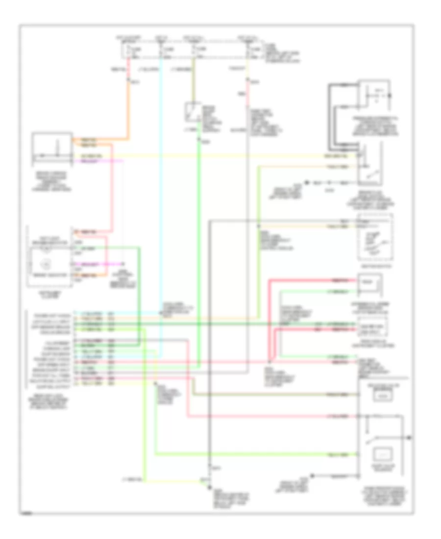
List of elements for Anti-lock Brake Wiring Diagrams for Ford Aerostar 1997:
- "anti-lock" brakes indicator
- "brake" indicator
- (main harn, in breakout to rabs module) s212
- (main harn, near breakout to instrument cluster) s231
- (top of rear axle)
- Acc
- Brake fluid level switch (left rear of engine compartment, on brake master cylinder)
- Brake on/off (boo) switch (on brake pedal support)
- Brake on/off input
- Brake warning resistor/diode assembly (taped to main harness, near g206)
- C250
- C251
- Diff sensor ground
- Diff speed input
- Differential speed sensor (dds)
- Dss input
- Dss return
- Dss test connector (left rear of engine compart- ment)
- Dump sol output
- Dump solenoid
- Dump valve solenoid
- Fuse 15a
- Fuse 20a
- Fuse panel (behind left side of i/p, left of steering column)
- G100 (front of left fender apron, left of battery)
- G206 (behind center of instrument panel, below left side of radio)
- Gnd
- Hot at all times
- Hot in run
- Hot in start or run
- Ignition switch
- Instrument cluster
- Isolation sol output
- Isolation valve solenoid
- Lock
- Low fluid lvl input
- Module ground
- Nca
- Off
- Power (hot in run)
- Pressure differential warning switch (left rear of engine compartment, below brake fluid reservoir)
- Psom module (instrument cluster)
- Pwr (hot all times)
- Rabs proportioning valve switch assembly (left rear of engine compartment, below master cylinder)
- Rabs test connector (behind left side of instrument panel, taped to main harness)
- Rear anti-lock brake module (rabs) (behind center of i/p, below ashtray)
- Red
- Red/pnk
- S105
- S213
- S216
- S228
- S232 (main harn, near breakout to instrument cluster)
- S233 (main harn, in breakout to rabs module)
- S262 (main harn, near breakout to wiper control module)
- S265 (main harn, near breakout to ground g206)
- S274
- Start run
- Valve reset
- Warning lamp
 English