TRANSMISSION
3.0L
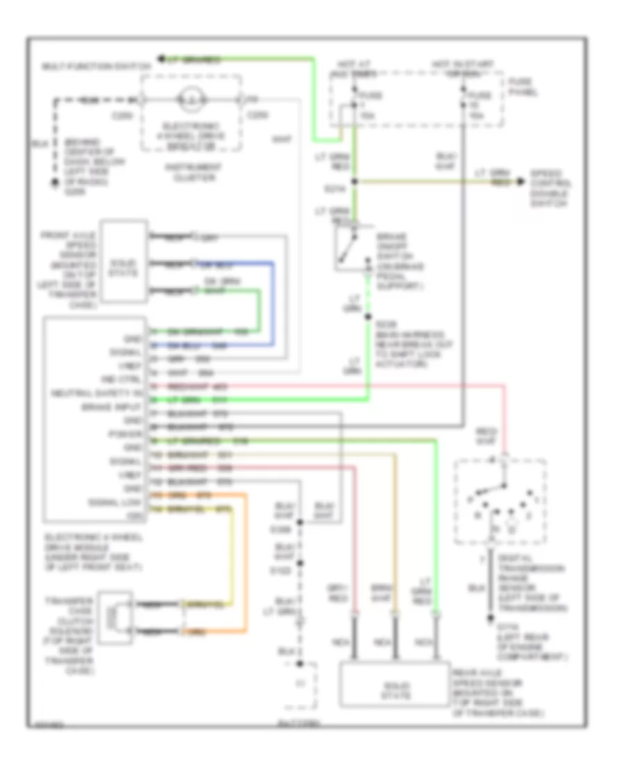
3.0L, Transfer Case Wiring Diagram for Ford Aerostar 1997

List of elements for 3.0L, Transfer Case Wiring Diagram for Ford Aerostar 1997:
- (-)
- (behind center of dash, below left side of radio) g206
- Battery
- Brake input
- Brake on/off switch (on brake pedal support)
- C250
- Digital transmission range sensor (left side of transmission)
- Electronic 4 wheel drive indicator
- Electronic 4 wheel drive module (under right side of left front seat)
- Front axle speed sensor (mounted on top left side of transfer case)
- Fuse 15a
- Fuse panel
- G114 (left rear of engine compartment)
- Gnd
- Hot at all times
- Hot in start or run
- Ign
- Ind ctrl
- Instrument cluster
- Mult-function switch
- Nca
- Neutral safety in
- Power
- Rear axle speed sensor (mounted on top right side of transfer case)
- S122
- S214
- S228 (main harness, near break out to shift lock actuator)
- S308
- Signal
- Signal low
- Solid state
- Speed control disable switch
- Transfer case clutch solenoid (top right side of transfer case)
- Vref
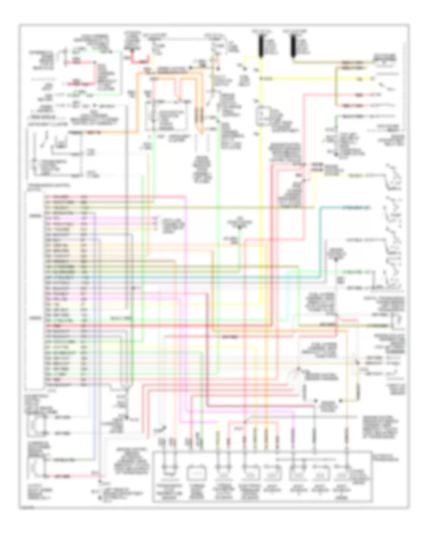
3.0L, Transmission Wiring Diagram for Ford Aerostar 1997
List of elements for 3.0L, Transmission Wiring Diagram for Ford Aerostar 1997:
- (5r55e)
- (engine control sensor extension harness, near breakout to 8-pin conn above front of transmission)
- (engine control sensor harness)
- (engine control sensor harness, near breakout to powertrain control module) s116
- (fuel charge harness, near break out to evap canister purge valve) s128
- (fuel charge harness, near breakout to fuel injector 6)
- (left rear of engine compartment on firewall) g114
- (main harness, near breakout to instrument cluster) s231
- (near windshield wiper motor)
- (top left center of firewall, near windshield wiper motor) g116
- 10a
- Air conditioning system
- Automatic transmission
- Brake on/off switch (on brake pedal support)
- Brake warning resistor/ diode assembly (left side of dash)
- C172
- C250
- C251
- Coast clutch solenoid (4r44e)
- Data link connector (center of (dash)
- Differential speed sensor (top of rear axle)
- Digital transmission range sensor (left side of transmission)
- Dss input
- Dss return
- Electronic pressure control solenoid
- Engine compartment relay box
- Engine controls system
- Engine coolant temperature sensor (top left front of engine)
- Fuel pump relay
- Fuse 15a
- G116
- Harness, near break- out to shift lock actuator)
- Hot at all times
- Hot in start or run
- I/p fuse panel
- Instrument cluster
- Liftgate wiper/ washer circuit breaker
- Malfunction indicator lamp (check engine)
- Multi- function switch
- Nca
- O/d off
- Output shaft speed sensor (5r55e only)
- Overdrive drum speed sensor (5r55e only)
- Pcm inline fuse (left rear of engine compartment)
- Pcm power relay
- Pcm power relay diode
- Powertrain control module (left of brake master cylinder)
- Psom module
- R p
- Red
- Red/ pnk
- S107
- S113
- S119 (fuel charge harness, near break- out to fuel injector 3)
- S122
- S123
- S124
- S125
- S126
- S127
- S201 (main harness, near breakout to speed control sw assembly)
- S213
- S232 (main harness, near breakout to inst cluster)
- Shift solenoid
- Shift solenoid (5r55e)
- Speed control disable switch
- Speed output
- Throttle postion sensor
- Torque converter clutch solenoid
- Transmission control indicator lamp
- Transmission control switch
- Transmission fluid temperature sensor
- Turbine shaft speed sensor
4.0L
4.0L, Transfer Case Wiring Diagram for Ford Aerostar 1997
List of elements for 4.0L, Transfer Case Wiring Diagram for Ford Aerostar 1997:
- (-)
- (behind center of dash, below left side of radio) g206
- Battery
- Brake input
- Brake on/off switch (on brake pedal support)
- C250
- Digital transmission range sensor (left side of transmission)
- Electronic 4 wheel drive indicator
- Electronic 4 wheel drive module (under right side of left front seat)
- Front axle speed sensor (mounted on top left side of transfer case)
- Fuse 15a
- Fuse panel
- G114 (left rear of engine compartment)
- Gnd
- Hot at all times
- Hot in start or run
- Ign
- Ind ctrl
- Instrument cluster
- Mult-function switch
- Nca
- Neutral safety in
- Power
- Rear axle speed sensor (mounted on top right side of transfer case)
- S122
- S214
- S228 (main harness, near break out to shift lock actuator)
- S308
- Signal
- Signal low
- Solid state
- Speed control disable switch
- Transfer case clutch solenoid (top right side of transfer case)
- Vref
4.0L, Transmission Wiring Diagram for Ford Aerostar 1997
List of elements for 4.0L, Transmission Wiring Diagram for Ford Aerostar 1997:
- (5r55e)
- (engine control sensor extension harness, near breakout to 8-pin conn above front of transmission)
- (engine control sensor harness)
- (engine control sensor harness, near breakout to powertrain control module) s116
- (fuel charge harness, near break out to evap canister purge valve) s128
- (fuel charge harness, near breakout to fuel injector 6)
- (left rear of engine compartment on firewall) g114
- (main harness, near breakout to instrument cluster) s231
- (near windshield wiper motor)
- (top left center of firewall, near windshield wiper motor) g116
- 10a
- Air conditioning system
- Automatic transmission
- Brake on/off switch (on brake pedal support)
- Brake warning resistor/ diode assembly (left side of dash)
- C172
- C250
- C251
- Coast clutch solenoid (4r44e)
- Data link connector (center of (dash)
- Differential speed sensor (top of rear axle)
- Digital transmission range sensor (left side of transmission)
- Dss input
- Dss return
- Electronic pressure control solenoid
- Engine compartment relay box
- Engine controls system
- Engine coolant temperature sensor (top left front of engine)
- Fuel pump relay
- Fuse 15a
- G116
- Harness, near break- out to shift lock actuator)
- Hot at all times
- Hot in start or run
- I/p fuse panel
- Instrument cluster
- Liftgate wiper/ washer circuit breaker
- Malfunction indicator lamp (check engine)
- Multi- function switch
- Nca
- O/d off
- Output shaft speed sensor (5r55e only)
- Overdrive drum speed sensor (5r55e only)
- Pcm inline fuse (left rear of engine compartment)
- Pcm power relay
- Pcm power relay diode
- Powertrain control module (left of brake master cylinder)
- Psom module
- R p
- Red
- Red/ pnk
- S107
- S113
- S119 (fuel charge harness, near break- out to fuel injector 3)
- S122
- S123
- S124
- S125
- S126
- S127
- S201 (main harness, near breakout to speed control sw assembly)
- S213
- S232 (main harness, near breakout to inst cluster)
- Shift solenoid
- Shift solenoid (5r55e)
- Speed control disable switch
- Speed output
- Throttle postion sensor
- Torque converter clutch solenoid
- Transmission control indicator lamp
- Transmission control switch
- Transmission fluid temperature sensor
- Turbine shaft speed sensor