POWER DISTRIBUTION
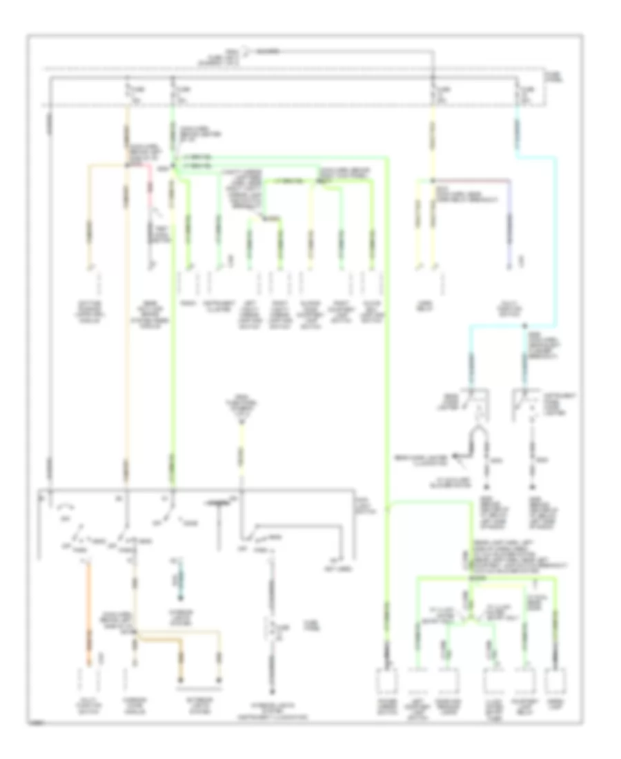
Power Distribution Wiring Diagram (1 of 3) for Ford Aerostar 1997

List of elements for Power Distribution Wiring Diagram (1 of 3) for Ford Aerostar 1997:
- (12 ga-
- (16 ga-
- (18 ga-
- (20 ga-
- (diagram 2 of 3)
- (eng cntrl sens harn, left rear of eng compt) s124
- (eng cntrl sensor harn, right front of eng compartment)
- (gen rectifier system harn, right front of eng compt)
- (main harn, behind center of i/p) s215
- (main harn, behind left kick panel)
- (main harn, behind left kick panel) s222
- (main harn, behind left side of i/p)
- (main harn, near data link connector breakout)
- (main harn, near inst cluster breakout) s272
- (main harn, near wiper control module breakout) s263
- (not used)
- (rabs) module breakout) s212
- (trailor lamp harn, near backup lamps relay breakout)
- 3.0l
- 4.0l
- A/c- heater control assembly
- Acc
- Air bag diagnostic monitor
- Auxiliary blower motor relay
- Backup lamps relay
- Battery
- Brake on/off (boo) switch
- C172
- C233
- C249
- C268
- Circuit breaker 14 20a
- Circuit breaker 2 6a
- Data link connector
- Digital trans- mission range (dtr) sensor
- Door lock/ unlock control relay
- Engine compartment relay box
- Fuel pump relay
- Fuse 10a
- Fuse 15a
- Fuse 20a
- Fuse link a
- Fuse link b
- Fuse link c
- Fuse link d
- Fuse link e
- Fuse link f
- Fuse link k
- Fuse panel
- Generator voltage regulator
- Ignition switch
- Illumi- nated entry timer
- In-line fuse 30a
- Instrument cluster
- Lock
- Master window/ door lock switch
- Multi- function switch
- Of i/p) s251
- Off
- Only
- Pcm inline fuse
- Pcm power relay
- Pnk
- Power door lock module
- Power- train control module (pcm)
- Radio
- Radio amplifier
- Rear anti- lock brake system (rabs) module
- Rear window defrost control
- Red
- Remote headphone module
- Right window/ door lock switch
- Run
- Running lamp relay
- S108
- S111 (engine control sensor harness, center of left fender)
- S133 (eng cntrl sensor harn, near starter relay breakout)
- S138 (eng cntrl sens harn, near starter relay breakout)
- S139
- S214 (main harn, behind left side of i/p)
- S221
- S269
- S280
- S410
- Sliding door ajar relay
- Speed control disable switch
- Speed control server/ amplifier assembly
- Sta
- Start
- Starter motor/ solenoid
- Starter relay
- To fuse panel
- To fuse panel (diagram 3 of 3)
- To fuse panel, and fuse link g, and instrument cluster (diagram 3 of 3)
- To main light switch (diagram 2 of 3)
- Wind- shield wiper motor
- Wiper control module
Power Distribution Wiring Diagram (2 of 3) for Ford Aerostar 1997
List of elements for Power Distribution Wiring Diagram (2 of 3) for Ford Aerostar 1997:
- (main harn, behind center of i/p)
- (main harn, behind left side of i/p) s216
- (main harn, behind left side of i/p) s219
- (main harn, behind right kick panel) s217
- (not used)
- (vanity mirror lamp feed harn, near right vanity mirror lamp and switch breakout)
- 22a
- C231
- C249
- Cargo lamp
- Courtesy lamp relay
- Daytime running lamps (drl) module
- Dimmer
- Dome
- Dome and reading lamps
- Exterior lights system
- From a fuse link a (diagram 1 of 3)
- From fuse panel (diagram 1 of 3)
- Fuse 15a
- Fuse 20a
- Fuse 30a
- Fuse 5a
- Fuse panel
- G206 (behind center of i/p, below left side of radio)
- Glove box lamp and switch
- Head
- Horn relay
- Ign
- Illumi- nated entry timer
- Instrument cluster
- Instrument panel cigar lighter
- Interior lights system
- Interior lights system (instrument illumination)
- Left courtesy lamp switch
- Left vanity mirror lamp and switch
- Main light switch
- Multi- function switch
- Nca
- Off
- Park
- Power mirror switch
- Radio
- Rear anti-lock brake system (rabs) module
- Rear cigar lighter
- Rear cigar lighter illumination
- Red
- Right courtesy lamp switch
- Right vanity mirror lamp and switch
- S202
- S218 (main harn, near horn relay breakout)
- S252
- S254
- S255 (main harn, near elect flasher breakout)
- S302
- S305
- Sliding door courtesy lamp switch
- Test conn- ector
- W/ auxiliary blower motor
- W/ dual rear door
- W/ illumi- nated entry only
- Warning chime module
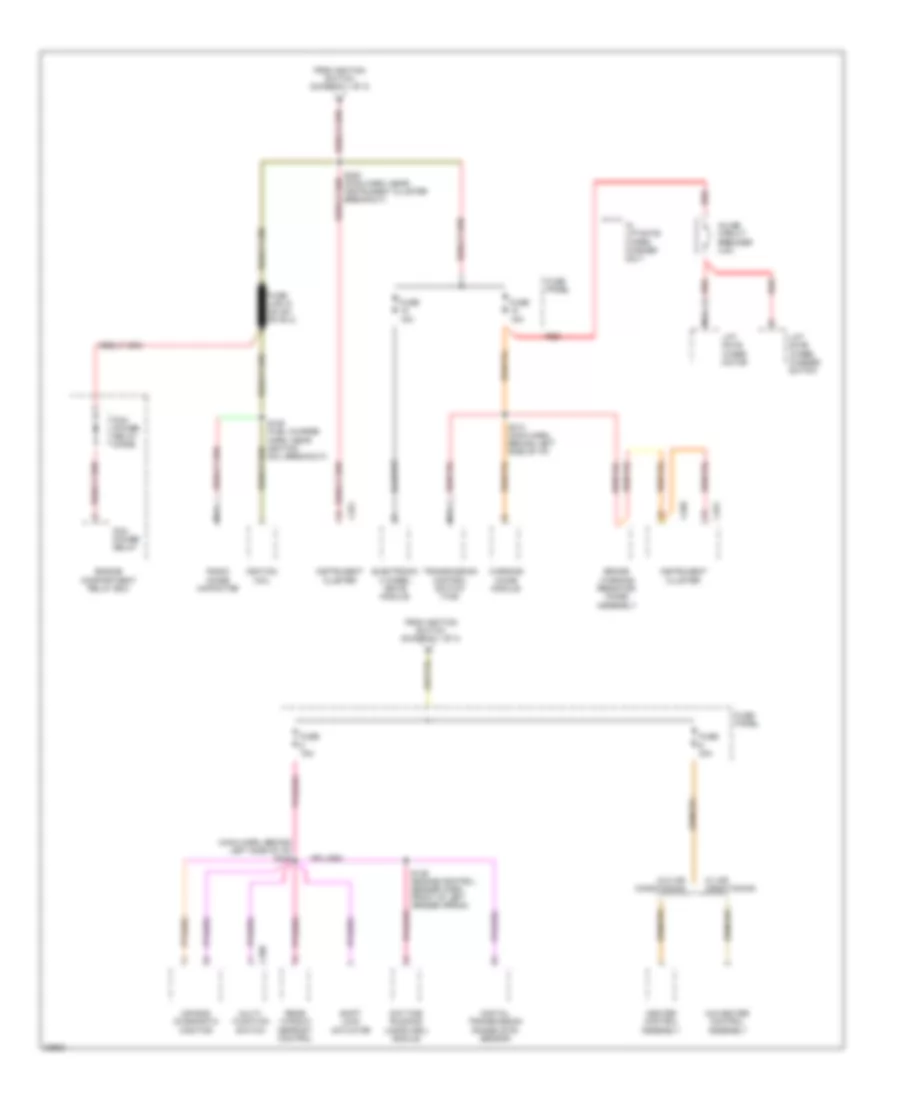
Power Distribution Wiring Diagram (3 of 3) for Ford Aerostar 1997
List of elements for Power Distribution Wiring Diagram (3 of 3) for Ford Aerostar 1997:
- (main harn, behind left side of i/p) s249
- A/c-heater control assembly
- Air bag diagnostic monitor
- Brake warning resistor/ diode assembly
- C250
- C251
- C268
- Daytime running lamps (drl) module
- Digital transmission range (dtr) sensor
- Electronic 4 wheel drive module
- Engine compartment relay box
- From ignition switch (diagram 1 of 3)
- Fuse 15a
- Fuse 30a
- Fuse panel
- Heater control assembly
- Ignition coil
- Inline circuit breaker 4.5a
- Instrument cluster
- Lift gate wiper motor
- Lift gate wiper/ washer switch
- Multi- function switch
- Nca
- Pcm power relay
- Pcm power relay diode
- Radio noise capacitor
- Rear window defrost control
- Red
- S109 (fuel charge harn, near ignition coil breakout)
- S136 (engine control sensor harn, front of left fender apron)
- S213 (main harn, behind left side of i/p)
- S220 (main harn, near instrument cluster breakout)
- Shift lock actuator
- Transmission control switch (tcs)
- W/ air conditioning
- W/ liftgate wiper/ washer only
- W/o air conditioning
- Warning chime module