AIR CONDITIONING
A/C Wiring Diagram for Ford Aerostar 1997

List of elements for A/C Wiring Diagram for Ford Aerostar 1997:
- (3.0l)
- (4.0l)
- (generator rectifier sys harn, on a/c clutch field coil breakout) s129
- (rear lamp harn, left rear of cargo area)
- (rear lamp harn, near aux blower motor relay breakout)
- (rear lamp harn, near auxiliary blower motor breakout)
- (top left center of safety wall)
- (top rear corner of right fender apron)
- A/c clutch diode
- A/c clutch field coil
- A/c wot cutout relay (in engine compartment relay box )
- A/c-heater control assembly
- Auxiliary a/c system refrigerant valve solenoid (behind left b pillar)
- Auxiliary blower motor
- Auxiliary blower motor relay (behind left b pillar)
- Auxiliary blower motor resistor assembly (behind left b pillar)
- Blower motor
- Blower motor resistor assembly (top right side of safety wall)
- Blower motor switch
- Clutch cycling pressure switch (right rear of engine compartment on a/c accumulator)
- Def
- Defrost
- Floor
- Front auxiliary blower motor switch
- Fuse 6 20a
- Fuse 9 30a
- Fuse panel
- G105
- G121
- G206 (behind center of i/p, left of radio)
- Heat
- High pressure cutoff switch (3.0l-right front of engine) (4.0l-left front of engine)
- Hot at all times
- Hot in accy or run
- Hot in run
- Max
- Med
- Mix
- Norm
- Off
- Pcm power relay
- Power- train control module (pcm) (top left side of safety wall)
- Rear
- Rear auxiliary blower motor switch
- Red
- S102 (eng control sens harn, top rear corner of right fender apron)
- S104 (generator rectifier sys harn, right front of eng compt)
- S106 (engine control sensor harness)
- S137 (eng control sens harn, near blower motor breakout)
- S215 (main harn, behind center of i/p)
- S243 (main harn, behind center of i/p)
- S283 (main harn, behind left side of i/p)
- S303 (rear lamp harn, left side of cargo area)
- S309 (rear lamp harn, near auxiliary blower motor breakout)
- S310
- S311
- S312 (rear lamp harn, near auxiliary blower motor resistor assembly breakout)
- S318
- Vent
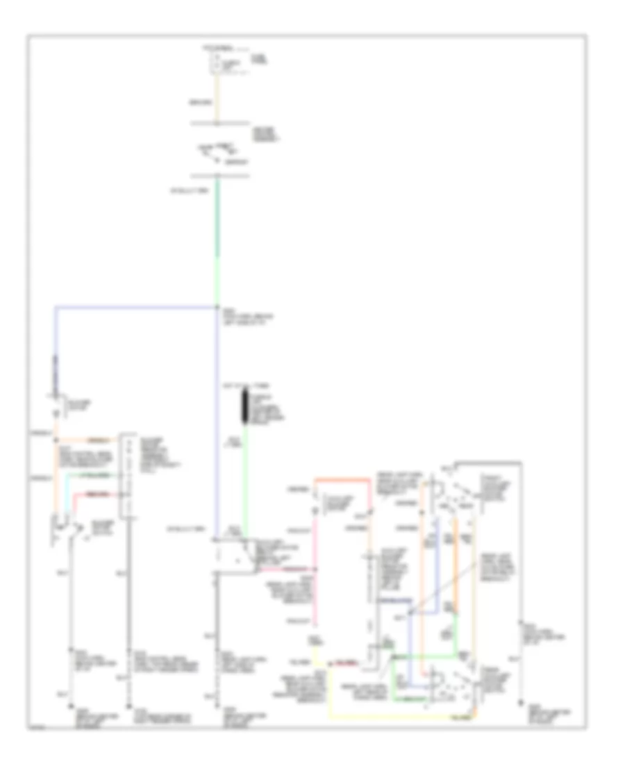
Heater Wiring Diagram for Ford Aerostar 1997
List of elements for Heater Wiring Diagram for Ford Aerostar 1997:
- (not used)
- (rear lamp harn, left rear of cargo area)
- (rear lamp harn, near aux blower motor relay breakout)
- (rear lamp harn, near auxiliary blower motor breakout)
- Auxiliary blower motor
- Auxiliary blower motor relay (behind left b pillar)
- Auxiliary blower motor resistor assembly (behind left b pillar)
- Blower motor
- Blower motor resistor assembly (top right side of safety wall)
- Blower motor switch
- Defrost
- Front auxiliary blower motor switch
- Fuse 9 30a
- Fuse panel
- G105 (top rear corner of right fender apron)
- G206 (behind center of i/p, left of radio)
- Heat
- Heater control assembly
- Hot at all times
- Hot in run
- Med
- Mix
- Off
- Rear
- Rear auxiliary blower motor switch
- S102 (eng control sens harn, top rear corner of right fender apron)
- S137 (eng control sens harn, near blower motor breakout)
- S243 (main harn, behind center of i/p)
- S283 (main harn, behind left side of i/p)
- S303 (rear lamp harn, left side of cargo area)
- S309 (rear lamp harn, near auxiliary blower motor breakout)
- S310
- S311
- S312 (rear lamp harn, near auxiliary blower motor resistor assembly breakout)
- S318
- Vent
 English