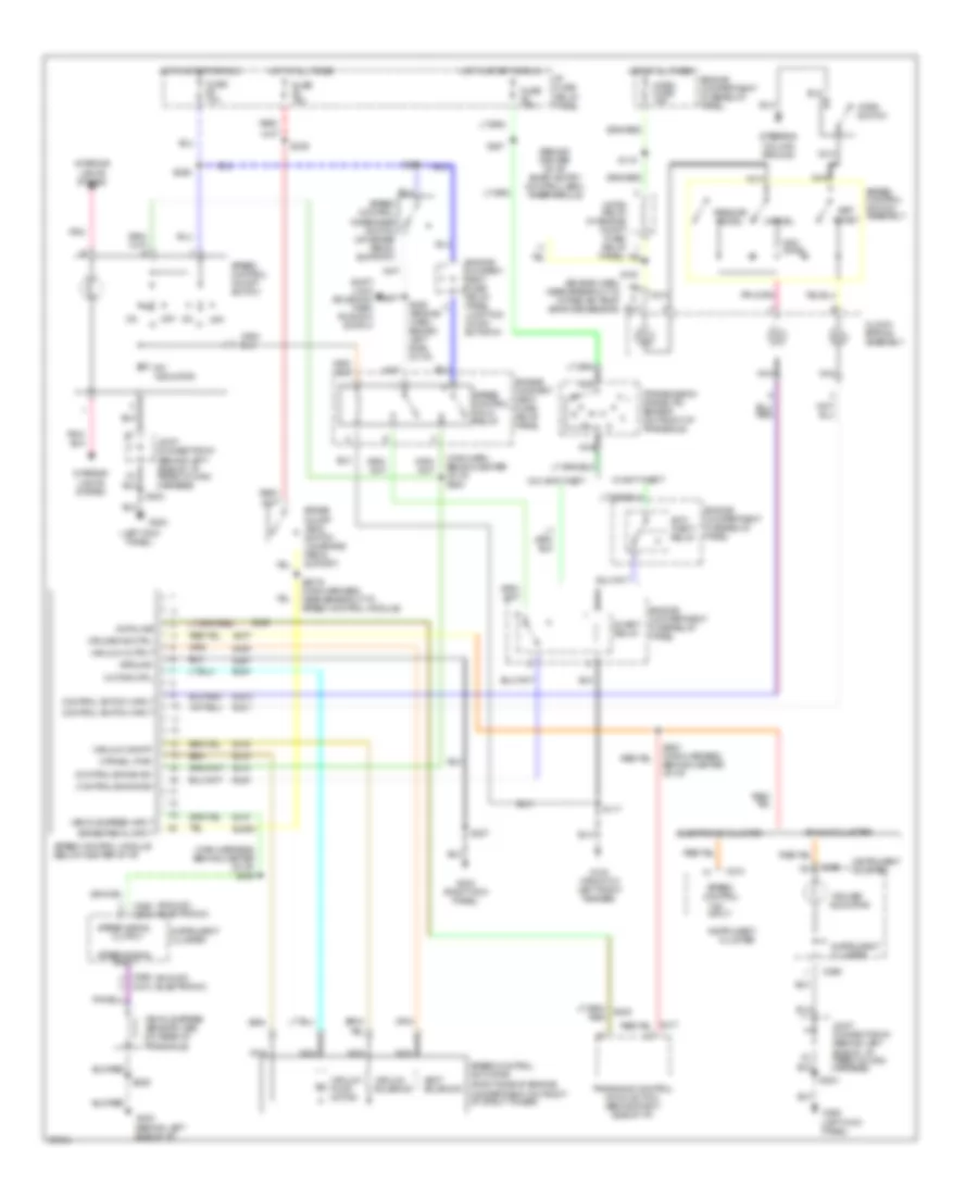
AUTOMOTIVE ELECTRICIANS PORTAL

CRUISE CONTROL – Mercury Villager Nautica 1997 – SYSTEM WIRING DIAGRAMS

CRUISE CONTROL

Cruise Control Wiring Diagram for Mercury Villager Nautica 1997

Cruise Control Wiring Diagram for Mercury Villager Nautica 1997 https://portal-diagnostov.com/license.html
https://portal-diagnostov.com/license.html Automotive Electricians Portal FZCO Automotive Electricians Portal FZCO
Get access to all wiring diagrams of the carDownload PDF file

List of elements for Cruise Control Wiring Diagram for Mercury Villager Nautica 1997:

  • "cruise" indicator
  • "on"
  • "on" input
  • (analog) (electronic)
  • (behind center of i/p) smart entry control (sec) timer module
  • (behind left side of i/p, taped to main harness)
  • (engine harn, near breakout to intake air temp- erature sensor)
  • (left kick panel)
  • (main harn, behind center of i/p) s282
  • (main harness, behind center of i/p) s254
  • (right side of engine, compartment on front of strut tower)
  • Analog cluster
  • Anti- theft relay
  • Brake on/off (boo) switch (on brake pedal suport)
  • Brake pedal input
  • C266
  • C268
  • C268 c272
  • C272
  • C274
  • Cancel
  • Clock- spring assembly
  • Cluster
  • Control en/dis sw
  • Control switch input
  • Cruise ind ctrl
  • Data line
  • Ej04
  • Ej06
  • Ej07
  • Ej08
  • Ej09a
  • Ej10
  • Ej14
  • Ej15
  • Ej16
  • Ej17
  • Ej40
  • Eje1
  • Ejo1
  • Ejo2
  • Electronic cluster
  • Engine compart- ment fuse/ relay panel
  • Engine compart- ment fuse/ relay panel junction conn- ector #1
  • Engine compartment fuse/relay panel
  • Fuse 10a
  • Fuse 15a
  • G100 (front of left front fender)
  • G200
  • G200 (left kick panel)
  • G202 (behind left side of i/p)
  • G203 (right kick panel)
  • Ground
  • Horn fuse 15a
  • Horn relay (in engine compt fuse/ relay
  • Horn switch
  • Hot at all times
  • Hot in start or run
  • I/p fuse/ relay panel
  • Indicator
  • Inhibit relay
  • Input
  • Instrument
  • Instrument cluster
  • Interior lights system
  • Joint connector #1
  • Joint connector #1 (behind left side of i/p, taped to main harness)
  • Motor ctrl
  • Mtr/sol pwr
  • Nca
  • Off
  • Ohms
  • Output
  • Panel)
  • Pnk
  • Red/
  • Resume/ accel
  • S115
  • S117
  • S140
  • S2016 (main harness, near breakout to speed control module)
  • S203
  • S207
  • S229
  • S239
  • S247
  • S258
  • S261
  • S283 (main harness, behind center of i/p)
  • S285 (engine harn, behind left side of i/p)
  • Set/ coast
  • Shift lock solenoid/ park position switch
  • Speed control
  • Speed control actuator
  • Speed control disengage switch (on brake pedal support)
  • Speed control hold relay
  • Speed control module (below center of i/p)
  • Speed control on/off switch
  • Speed control switch assembly
  • Speed signal
  • Steering column ground
  • Transaxle control module (tcm) (behind right side of i/p)
  • Transaxle)
  • Transmission range (tr) sensor (on front of transaxle)
  • Vacuum on/off
  • Vacuum output
  • Vacuum pump motor
  • Vacuum solenoid
  • Vehicle speed input
  • Vehicle speed sensor (vss) (on rear of
  • Vent solenoid
  • W/ anti-theft
  • W/o anti-theft