POWER WINDOWS
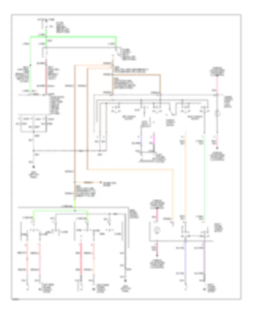
Power Window Wiring Diagram for Mercury Villager Nautica 1997
List of elements for Power Window Wiring Diagram for Mercury Villager Nautica 1997:
- 18a
- Auto
- Auto down module
- Base of "a" pillar)
- C2030
- C2031
- C2032
- Close
- G200 (left kick panel)
- Hot at all times
- In-line circuit breaker 1 (behind left side of dash)
- Interior lights system (instrument illumination)
- Left power window motor
- Left rear power window motor
- Left window switch
- Master window/ door lock switch
- Nca
- Open
- Pnk
- Power tops system
- Power window relay (behind left side of dash)
- Rear power window control
- Red
- Right power window motor
- Right power window switch
- Right rear power window motor
- Right window switch
- S201
- S2012 (main harn, near breakout to in-line conn behind ctr of dash)
- S2017 (main harn, near breakout to joint conn 1)
- S206
- S227
- S299 (eng ctrl harn, near breakout to powertrain ctrl module)
- S501
- S502 (left fr dr harn, near breakout to in-line conn, behind left side of dash)
- S900
- Sce1
- Sce2
- Sce7
- Smart entry control (sec)/timer module (behind center bottom of dash)
- Window lockout switch
 English