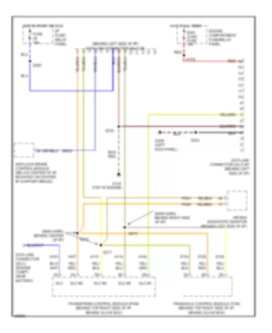
COMPUTER DATA LINES
Computer Data Lines for Mercury Villager Nautica 1997
List of elements for Computer Data Lines for Mercury Villager Nautica 1997:
- (behind left side of i/p) data link connector (dlc) #2
- (main harn, behind center of i/p)
- (main harn, behind right side of i/p)
- Air bag diagnostic monitor (behind left side of i/p)
- Anti-lock brake control module (below center of i/p, mounted on center i/p support brace)
- Av07
- Av14
- Av15
- Av23
- Av42
- Bs30
- Data link connector (dlc) #1 (behind left side of i/p)
- Data link connector (dlc) (engine compt, near battery)
- Dlc
- Dlc #1
- Dlc #2
- Eng cont fuse 10a
- Engine compartment fuse/relay panel
- Fuse 10a
- G134 (top of engine)
- G200 (left kick panel)
- Hot at all times
- Hot in start or run
- I/p fuse/ relay panel
- Powertrain control module (pcm) (behind top right side of i/p, behind glove box)
- Ps20
- Ps21
- Red
- S112
- S203
- S230
- S262
- S271
- S272
- S273
- Transaxle control module (tcm) (behind top right side of i/p, behind glove box)
- Zy28
- Zy29
- Zy30
 English