AIR CONDITIONING
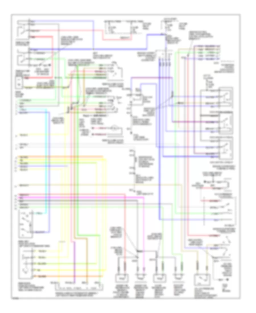
A/C Wiring Diagram, Auto A/C (1 of 2) for Mercury Villager Nautica 1997

List of elements for A/C Wiring Diagram, Auto A/C (1 of 2) for Mercury Villager Nautica 1997:
- (center of i/p)
- (main harn, behind right side of i/p)
- (right side of i/p)
- Acc
- All times
- Autolamp module
- Blower motor
- Blw fuse 65a
- C2027
- C2028
- C2029
- C212
- E/m switch
- Eatc module
- Electronic automatic temperature control module (center of i/p)
- Engine compart- ment fuse/ relay panel
- F/r door
- F/r door actuator
- Floor/panel
- Fresh/recirculation door actuator (behind right side of i/p, on plenum)
- Front blend door actuator (behind right side of i/p, on plenum)
- Front blower motor relay
- Front blower motor/ speed controller
- Frt blend door
- Frt blend door (cool)
- Frt blend door (warm)
- Frt blo motor relay
- Fuse 10a
- Fuse 20a
- Fuse 7.5a
- G201
- G202 (left side of i/p)
- Ground
- Ha01
- Ha02
- Ha04
- Ha06
- Ha09
- Ha11
- Ha12
- Ha13
- Ha14
- Ha15
- Ha16
- Ha17
- Ha18
- Ha20
- Ha21
- Ha22
- Ha23
- Ha24
- Ha28
- Hae2
- Hc02
- Hc03
- Hc04
- Hc05
- Hc06
- Hc08
- Hc09
- Hc10
- Hc11
- Hc12
- Hc13
- Hc14
- Hc15
- Hc16
- Hc17
- Hc18
- Hc19
- Hc20
- Hc21
- Hce2
- Hce5
- Hce7
- Hj02
- Hj03
- Hj05
- Hj06
- Hj07
- Hj10
- Hj12
- Hot at
- Hot at all times
- Hot in run
- I/p fuse/ relay panel
- I/p fuse/relay panel
- Ignition
- Ignition switch
- Ih01
- Ih02
- Ih91
- Illumination
- In car temp sensor
- Instrument cluster
- Interior lights system
- J/c 1 (left i/p)
- Lo pressure
- Lock
- Mode actuator
- Mode actuator (behind center of i/p)
- Nca
- Off
- Pnk
- Position switches
- Power
- Rea water vlv sol
- Rear blend dr act
- Rear climate control panel
- Rear vent door act
- Rr blend door
- Rr blower motor
- Rr blower motor relay
- Rr blw motor sw
- Rr cc panel
- Rr cc power
- Rr cc switch (frt)
- Rr climate ctrl panel
- Run
- S203 (main harn, behind right side of i/p)
- S209
- S231 (main harn, behind right side of i/p)
- S236 (main harn, near front blower motor breakout)
- S249 (main harn, behind right side of i/p)
- S315
- S316
- Sensor input
- Sensor power
- Side of i/p)
- Start
- Sunload sensor
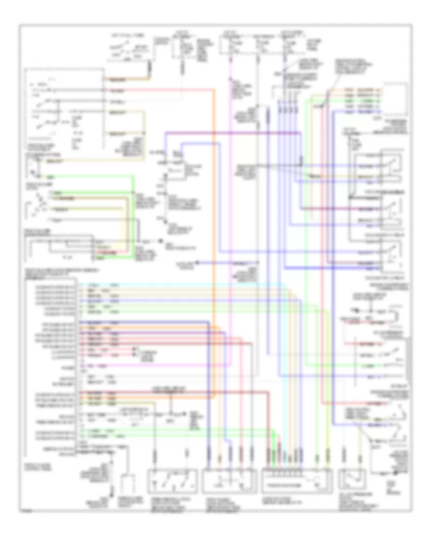
A/C Wiring Diagram, Auto A/C (2 of 2) for Mercury Villager Nautica 1997
List of elements for A/C Wiring Diagram, Auto A/C (2 of 2) for Mercury Villager Nautica 1997:
- (center rear of engine)
- (eng control harn, right rear of eng)
- (eng room harn, left side of eng compt)
- (engine control harn, in powertrain control module (pcm) breakout)
- (front center
- (main harn, behind center of i/p)
- (main harn, behind left side of i/p)
- (main harn, behind right side of i/p)
- (main harn, near elect auto temp module breakout)
- (main harn, near left cowl panel)
- (main harn, near rear blower motor resistor assembly breakout)
- (main harn, near rear blower motor switch relay breakout)
- (right side
- (sub harn (eatc), behind center of i/p)
- A/c compressor clutch coil
- A/c high pressure switch (right front of engine)
- A/c low pressure switch (right side of engine compartment, on accumulator)
- A/c relay
- Ambient air temperature sensor 1
- Ambient air temperature sensor 2
- C275
- Compartment)
- Cooling fan hi1 relay
- Cooling fan hi2 relay
- Cooling fan lo relay
- Cooling fan motor
- Engine compart- ment fuse/relay junction connector 1
- Engine compartment fuse/relay panel
- Fa06
- Fa12
- Fuse 10a
- Fuse 15a
- G104 (left rear of eng compt)
- G134 (top of engine)
- G201
- G202 (left side of i/p)
- G202 (left side of i/p)
- G407 (center rear of vehicle)
- Ha41
- Ha45
- Hot at all times
- Hot in start or run
- Hx01
- I/p fuse/ relay panel
- In-car
- Interior lights system
- Nca
- Of engine
- Of i/p)
- Off
- Pnk
- Powertrain control module (pcm) (behind glove box)
- Rad fuse 65a
- Rear
- Rear blend door actuator (left side of passenger area, on rear plenum)
- Rear blower motor
- Rear blower motor relay
- Rear blower motor resistor assembly (left side of rear passenger area)
- Rear blower motor switch (front)
- Rear blower motor switch (rear)
- Rear blower motor switch relay
- Rear engine coolant valve solenoid (center rear of engine)
- Rear vent door actuator (left side of passenger area)
- Red
- S102 (eng room harn, near oil press switch breakout)
- S135
- S158
- S159
- S2015
- S210 (eng cntrl harn, right front of engine)
- S212
- S219
- S224 (main harn, behind right side of i/p)
- S237 (main harn, behind right side of i/p)
- S251
- S253 (main harn, near elect auto temp cntrl breakout)
- S288
- S289
- S290
- S304
- S311
- S313
- S314
- S318
- Sensor (behind ashtray, in i/p)
- Sunload sensor (right side of cargo area)
- Temperature
A/C Wiring Diagram, Manual A/C for Mercury Villager Nautica 1997
List of elements for A/C Wiring Diagram, Manual A/C for Mercury Villager Nautica 1997:
- (eng control harn, right rear of eng)
- (eng room harn, left side of eng compt)
- (engine control harn, in powertrain control module (pcm) breakout)
- (left rear of eng compt)
- (left side of i/p)
- (main harn, behind right side of i/p)
- (right side of i/p)
- A/c compressor clutch coil
- A/c high pressure switch (right front of engine)
- A/c low pressure switch (right side of engine compartment, on accumulator)
- A/c relay
- A/c request
- Acc
- All times
- Autolamp module
- Blw fuse 65a
- C201
- C203
- C275
- Cooling fan hi1 relay
- Cooling fan hi2 relay
- Cooling fan lo relay
- Cooling fan motor
- Engine compart- ment fuse/ relay panel
- Engine compart- ment fuse/relay junction connector 1
- Engine compartment fuse/relay panel
- Fa06
- Fa12
- Fresh/recirc dr act
- Fresh/recirculation door actuator (behind right side of i/p, on plenum)
- Front blend door actuator (behind right side of i/p, on plenum)
- Front blower motor
- Front blower motor relay
- Front blower motor resistor assembly (behind right side of i/p, in plenum)
- Front blower motor switch
- Front climate control panel
- Frt blend dr act
- Frt blend dr mtr act
- Frt blower mtr ctrl
- Fuse 10a
- Fuse 20a
- Fuse 7.5a
- G104
- G134 (top of engine)
- G201
- G201 (right side of i/p)
- G202 (behind left side of i/p)
- Ground
- Ha01
- Ha02
- Ha04
- Ha05
- Ha06
- Ha09
- Ha11
- Ha12
- Ha13
- Ha14
- Ha15
- Ha16
- Ha17
- Ha18
- Ha20
- Ha21
- Ha22
- Ha23
- Ha24
- Ha28
- Ha41
- Ha45
- Hae4
- Hb21
- He01
- Hot at
- Hot at all times
- Hot in run
- Hot in start or run
- Hx01
- I/p fuse/ relay panel
- I/p fuse/relay panel
- Ignition
- Ignition switch
- Ih01
- Ih91
- Illumination
- Interior lights system
- J/c 1
- Lock
- Mode act motor
- Mode actuator (behind center of i/p)
- Mode actuator sw in
- Nca
- Off
- Pnk
- Position switches
- Power
- Powertrain control module (pcm) (behind glove box)
- Rad fuse 65a
- Rear blower motor switch (front)
- Rear blw mtr sw
- Run
- S102 (eng room harn, near oil press switch breakout)
- S135
- S158
- S159
- S203
- S219
- S231 (main harn, behind right side of i/p)
- S236 (main harn, near front blower motor breakout)
- S248 (main harn, behind left side of i/p)
- S249 (main harn, behind right side of i/p)
- S251
- S287 (main harn, behind right side of i/p)
- S301 (main harn, near rear vent door actuator breakout)
- Start
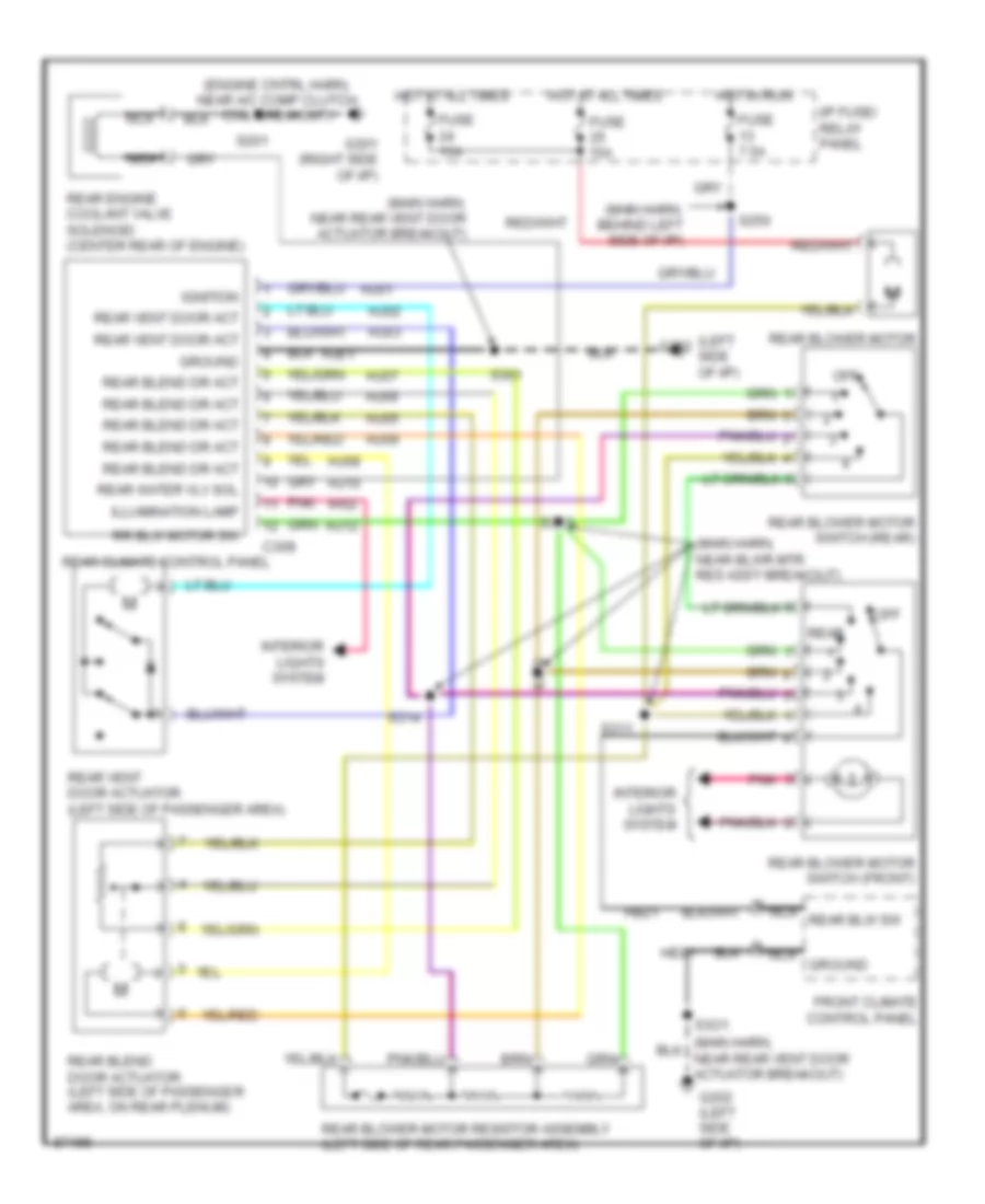
Rear A/C Wiring Diagram, Manual A/C for Mercury Villager Nautica 1997
List of elements for Rear A/C Wiring Diagram, Manual A/C for Mercury Villager Nautica 1997:
- (engine cntrl harn, near a/c comp clutch coil breakout)
- (left side of i/p)
- (main harn, behind left side of i/p)
- (main harn, near blwr mtr res ass'y breakout)
- (main harn, near rear vent door actuator breakout)
- C308
- Front climate control panel
- Fuse 15a
- Fuse 7.5a
- G201 (right side of i/p)
- G202
- G202 (left side of i/p)
- Ground
- Hb21
- He01
- Hj01
- Hj02
- Hj03
- Hj05
- Hj06
- Hj07
- Hj08
- Hj09
- Hj10
- Hj12
- Hje1
- Hot at all times
- Hot in run
- I/p fuse/ relay panel
- Ignition
- Ih02
- Illumination lamp
- Interior lights system
- Nca
- Nca ground
- Nca rear blw sw
- Off
- Pnk
- Rear
- Rear blend door actuator (left side of passenger area, on rear plenum)
- Rear blend dr act
- Rear blower motor
- Rear blower motor resistor assembly (left side of rear passenger area)
- Rear blower motor switch (front)
- Rear blower motor switch (rear)
- Rear climate control panel
- Rear engine coolant valve solenoid (center rear of engine)
- Rear vent door act
- Rear vent door actuator (left side of passenger area)
- Rear water vlv sol
- Rr blw motor sw
- S201
- S250
- S301
- S311
- S313
- S314
- S318
- S3o1