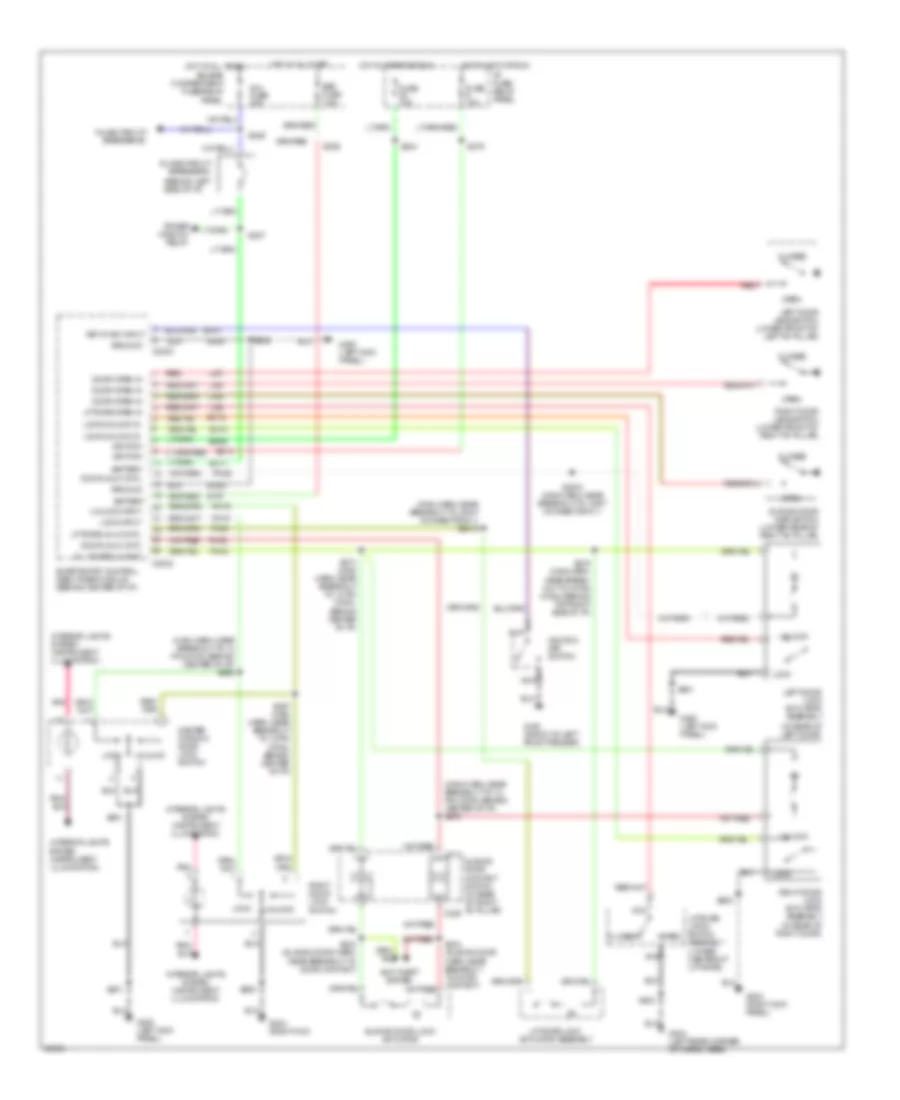
POWER DOOR LOCKS
Door Lock Wiring Diagram for Mercury Villager Nautica 1997

List of elements for Door Lock Wiring Diagram for Mercury Villager Nautica 1997:
- (behind left side of i/p)
- (in rear of left door)
- (instrument illumination)
- (main harn, near breakout to 12 pin conn, behind center of i/p) s276
- (not used)
- All doors lk cntl
- Battery
- C2032
- C311
- C329
- Closed
- Door open in
- Door unlk cntl
- Engine compartment fuse/relay panel
- G200 (left kick panel)
- G203 (right kick panel)
- G404 (left rear corner of cargo area)
- Ground
- Hot at all times
- Inline circuit breaker #1
- Inline circuit breaker #2
- Interior lights
- Interior lights system (instrument illumination)
- Left door jamb switch (lower front of left "b" pillar)
- Left door lock actuator assembly
- Lftgate open in
- Lftgate unlk cntl
- Li87
- Li89
- Li90
- Li94
- Liftgate latch switch assembly (lower center of liftgate)
- Liftgate lock actuator assembly
- Lock
- Lock input
- Lock/unlock in
- Master window/ door lock switch
- Nca
- Open
- P/w fuse 30a
- Ph10
- Ph19
- Ph32
- Ph35
- Ph38
- Ph43
- Pnk
- Power window relay
- Red
- Right door lock switch
- Right door jamb switch (lower front of right "b" pillar)
- Right door lock actuator assembly (in rear of right door)
- S201
- S2018 (main harn, near breakout to joint connector # 1)
- S2019 (main harn, near breakout to joint connector # 1)
- S206
- S226
- S227
- S267 (main harn, near breakout to 12 pin conn, behind center of i/p)
- S268 (main harn, near breakout to 12 pin conn, behind center of i/p)
- S274 (main harn, near breakout to 12 pin conn, behind center of i/p)
- S275 (main harn, near breakout to 16 pin conn, behind top right side of i/p)
- S333 (sliding door harn, near breakout to door contact)
- S334 (sliding door harn, near breakout to door contact)
- S403
- S501
- S600
- Sc11
- Sc15
- Sc16
- Sce2
- Sliding door ajar switch (lower rear of right "b" pillar)
- Sliding door contact switch (in rear of right "b" pillar)
- Sliding door lock actuator
- Smart entry control (sec)/ timer module (behind center of i/p)
- System
- Unlock
- Unlock input
Keyless Entry Wiring Diagram for Mercury Villager Nautica 1997
List of elements for Keyless Entry Wiring Diagram for Mercury Villager Nautica 1997:
- (behind left side of i/p)
- (in rear of left door)
- (instrument illumination)
- (main harn, near breakout to 12 pin conn, behind center of i/p) s268
- (main harn, near breakout to 12 pin conn, behind center of i/p) s276
- (main harn, near breakout to joint connector # 1) s2018
- All doors lk cntl
- Anti-theft system
- Battery
- Breaker #1
- Breaker #2
- C2030
- C2032
- C311
- C329
- Closed
- Door open in
- Door unlk cntl
- Engine compartment fuse/relay panel
- Er05
- Er10
- Fuse 10a
- G100 (front of left front fender)
- G200 (left kick panel)
- G203 (right kick
- G203 (right kick panel)
- G404 (left rear corner of cargo area)
- Ground
- Hot at all times
- Hot in acc or run
- Hot in start or run
- I/p fuse/ relay panel
- Ignition
- Ignition key switch
- Inline circuit
- Interior lights
- Interior lights system (instrument illumination)
- Key-in ign input
- Left door jamb switch (lower front of left "b" pillar)
- Left door lock actuator assembly
- Lftgate open in
- Lftgate unlk cntl
- Li87
- Li89
- Li90
- Li94
- Liftgate latch switch assembly (lower center of liftgate)
- Liftgate lock actuator assembly
- Lock
- Lock input
- Lock/unlock in
- Master window/ door lock switch
- Nca
- Open
- P/w fuse 30a
- Ph10
- Ph19
- Ph32
- Ph35
- Ph38
- Ph43
- Pnk
- Power
- Red
- Relay
- Right door lock switch
- Right door jamb switch (lower front of right "b" pillar)
- Right door lock actuator assembly (in rear of right door)
- S201
- S2019 (main harn, near breakout to joint connector # 1)
- S206
- S226
- S227
- S244
- S267 (main harn, near breakout to 12 pin conn, behind center of i/p)
- S274 (main harn, near breakout to 12 pin conn, behind center of i/p)
- S275 (main harn, near break- out to 16 pin conn, behind top right side of i/p)
- S279
- S333 (sliding door harn, near breakout to door contact)
- S334 (sliding door harn, near breakout to door contact)
- S403
- S501
- S600
- Sc11
- Sc13
- Sc15
- Sc16
- Sce1
- Sce2
- Sec fuse 7.5a
- Sliding door ajar switch (lower rear of right "b" pillar)
- Sliding door contact switch (in rear of right "b" pillar)
- Sliding door lock actuator
- Smart entry control (sec)/timer module (behind center of i/p)
- St70
- System
- Unlock
- Unlock input
- Window