SHIFT INTERLOCK
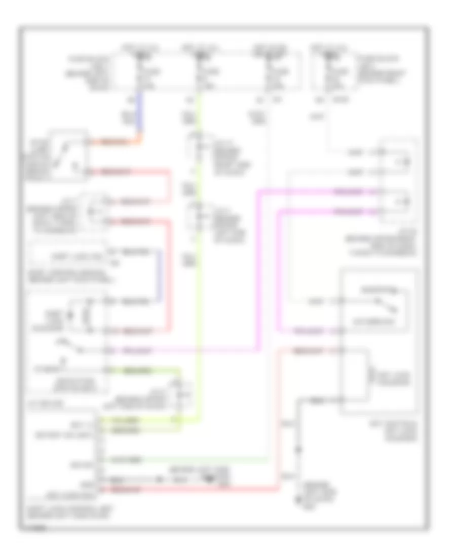
Shift Interlock Wiring Diagram for Infiniti M45 2003
List of elements for Shift Interlock Wiring Diagram for Infiniti M45 2003:
- (behind left side of dash) m24
- (behind left side of dash) m25
- A/t device
- Bat (+)
- Body control module (behind left kick panel)
- Detection switch (key)
- Detent sw (key)
- Fuse 10a
- Fuse 15a
- Fuse block (j/b) 1 (behind left end of dash)
- Fuse block j/b 2 (behind right kick panel)
- Gnd
- Hot at all times
- Hot in on or start
- Ign sw
- Inserted
- J/c 11 (behind upper right side of dash)
- J/c 2 (behind upper left end of dash)
- J/c 20 (behind upper right side of dash, taped to harness)
- J/c 3 (behind upper left end of dash)
- J/c 7 (behind upper left side of dash, taped to harness)
- Key lock sol
- Key lock solenoid
- Key switch & key lock solenoid
- M145
- Others
- Shift lock control unit (behind left side dash)
- Shift lock sol
- Shift lock solenoid
- Stop lamp switch (above brake pedal)
- Withdrawn
 Dansk
Dansk Deutsch
 Ελληνικά
 English
 English
 Español
 Suomi
Suomi Français
 Français
 עברית
עברית Hrvatski
 Magyar
 Italiano
 日本語
日本語 한국어
한국어 Nederlands
 Polski
 Português
 Português
 Română
 Русский
 Slovenčina
 Slovenščina
 Svenska
 Türkçe
 中文 (中国)
 Čeština