SHIFT INTERLOCK
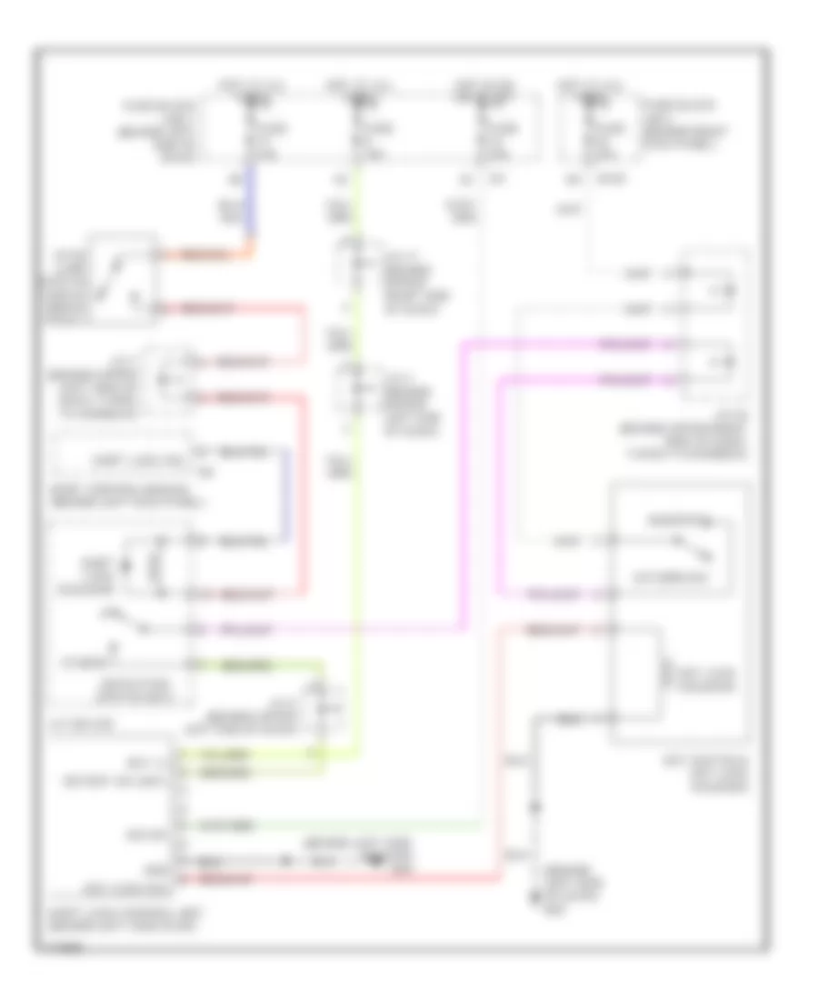
Shift Interlock Wiring Diagram for Infiniti M45 2003
List of elements for Shift Interlock Wiring Diagram for Infiniti M45 2003:
- (behind left side of dash) m24
- (behind left side of dash) m25
- A/t device
- Bat (+)
- Body control module (behind left kick panel)
- Detection switch (key)
- Detent sw (key)
- Fuse 10a
- Fuse 15a
- Fuse block (j/b) 1 (behind left end of dash)
- Fuse block j/b 2 (behind right kick panel)
- Gnd
- Hot at all times
- Hot in on or start
- Ign sw
- Inserted
- J/c 11 (behind upper right side of dash)
- J/c 2 (behind upper left end of dash)
- J/c 20 (behind upper right side of dash, taped to harness)
- J/c 3 (behind upper left end of dash)
- J/c 7 (behind upper left side of dash, taped to harness)
- Key lock sol
- Key lock solenoid
- Key switch & key lock solenoid
- M145
- Others
- Shift lock control unit (behind left side dash)
- Shift lock sol
- Shift lock solenoid
- Stop lamp switch (above brake pedal)
- Withdrawn
 English