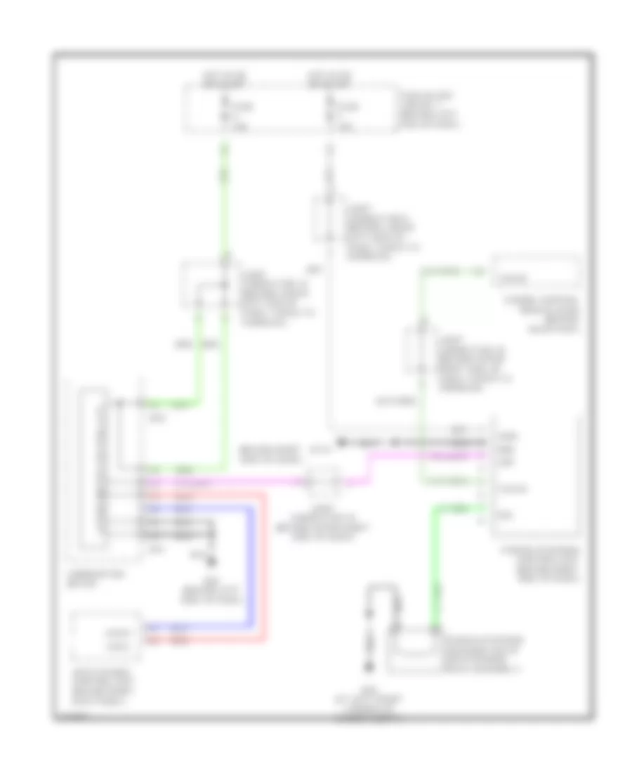
ELECTRONIC POWER STEERING
Electronic Power Steering Wiring Diagram for Infiniti M45 2003
List of elements for Electronic Power Steering Wiring Diagram for Infiniti M45 2003:
- (behind right side of dash)
- Can-h
- Can-l
- Combination meter
- E62 (at left front corner of engine compt)
- Engine control module (ecm) (behind glove box)
- Fuse 10a
- Fuse block (j/b) no. 1 (behind left end of dash)
- Gnd
- Hot in on or start
- Joint connector 10 (behind upper left end of dash, taped to harness)
- Joint connector 16 (behind upper right side of dash)
- Joint connector 19 (behind upper right side of dash, taped to harness)
- Joint connector 9 (behind lower left side of dash, taped to harness)
- M114
- M24 (behind left side of dash)
- M41
- M42
- Power steering control unit (behind right side of dash)
- Power steering solenoid valve (on steering rack assembly)
- Red
- Sol
- Tacho
- Unified meter control unit
- Vdc/tcs/abs control unit (behind right kick panel)
- Vign
- Vsp
 English