AIR CONDITIONING
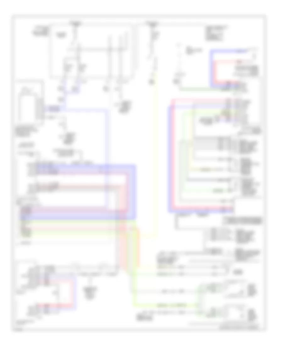
Automatic A/C Wiring Diagram (1 of 2) for Infiniti M45 2003

List of elements for Automatic A/C Wiring Diagram (1 of 2) for Infiniti M45 2003:
- (behind left side of dash) m25
- (behind right side of dash) m114
- (behind right side of dash) m115
- A/c auto amplifier (behind right side of dash, near blower motor)
- A/c-av (fr tx)
- Acc
- Air mix door motor (passenger side) (behind right side of dash, on heater unit)
- Amb sens
- Ambient sensor (behind center of front bumper)
- Av-a/c (fr rx)
- Bat
- Clk (fr)
- Combination meter
- Comp on comp on
- Compressor
- Computer data lines system
- Ecm comp
- Ecv
- Ecv solenoid valve
- F10
- Fan on
- Fan pwm
- Fuse 10a
- Fuse block (j/b) no.1 (behind left end of dash)
- Gnd
- Hot at all times
- Hot in acc or on
- Hot in on or start
- Ign
- In-vehicle sensor (behind lower center of dash)
- Incar sens
- Intake door motor (under right side of dash, on intake unit)
- Intake sens
- J/c 11 (behind upper right side of dash, taped to harness)
- J/c 14 (behind upper right side of dash, taped to harness)
- J/c 16 (behind upper right side of dash, taped to harness)
- J/c 19 (behind upper right side of dash, taped to harness)
- Lan sig
- M119
- M120
- M41
- M42
- Magnetic clutch
- Mode door motor (passenger side) (behind lower right side of dash, on heater unit)
- Pnk
- Red
- Sens gnd
- Speed sens
- Sun load sensor (under top left side of dash)
- Sun sens
- Unified meter control unit
- Vactr
- W/t sens
Automatic A/C Wiring Diagram (2 of 2) for Infiniti M45 2003
List of elements for Automatic A/C Wiring Diagram (2 of 2) for Infiniti M45 2003:
- (behind right side of dash) m114
- (behind right side of dash) m115
- 11r
- 18r
- Ac-av
- Acclk
- Acrly
- Air conditioner relay
- Air mix door motor (driver side)
- Av & navi control unit (or av control unit)
- Av-ac
- Avcc
- Blower motor (below right side of dash, on intake unit)
- Blower relay
- Bus +
- Bus -
- Bus shield
- Can-h
- Can-l
- Computer data lines system
- Connector used w/av & navi control unit
- Cooling fan speed control solenoid valve (on front of engine)
- Display
- Engine control module (behind glove box)
- Engine coolant temperature sensor (on top rear of engine)
- F101
- F102
- F8 (at left front of engine, near oil level gauge)
- Fuse 10a
- Fuse 15a
- Fuse block (j/b) 2 (behind right kick panel)
- Fuse, fusible link & relay block (j/b) (at right side of engine compartment)
- Gnd-a
- Heater & cooler unit assembly
- Hot at all times
- Intake sensor
- J/c 28 (behind upper right side of dash, near pass-through grommet)
- J/c 29 (behind upper right side of dash, near pass-through grommet)
- J/c 30 (behind upper right side of dash, near pass-through grommet)
- M115 (behind right side of dash)
- M144
- M145
- M83
- Mode door motor (driver side)
- Multifunction switch
- Nca
- Pdpres
- Pnk
- Prf+
- Prf-
- Radiator coolant temperature sensor (at bottom left side of radiator)
- Red
- Refrigerant pressure sensor (front right side of engine compartment, near condenser)
- Shield
- Twrf
- W/av & navi control unit
- W/av control unit