WARNING SYSTEMS
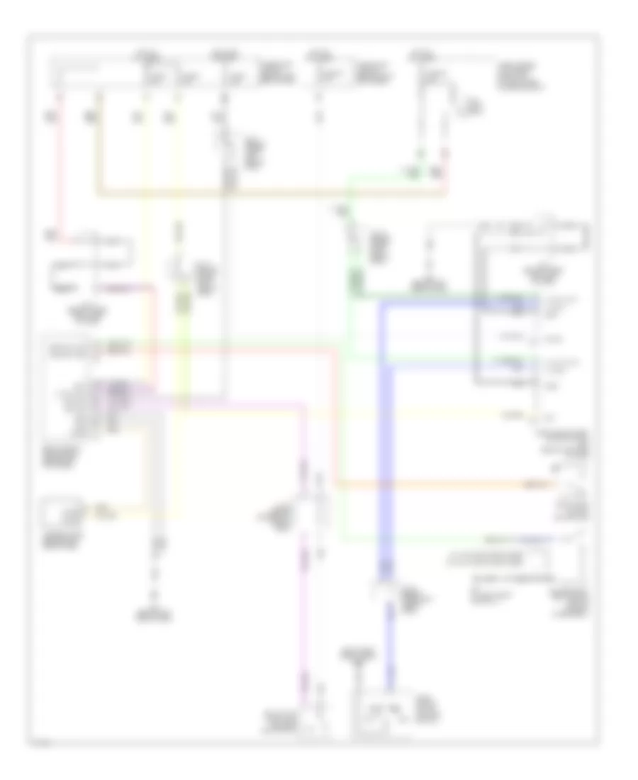
Warning Systems Wiring Diagram for Infiniti M45 2003
List of elements for Warning Systems Wiring Diagram for Infiniti M45 2003:
- (right right side of dash) m115
- (w/ auto drive positioner)
- (w/o auto drive positioner)
- 12r
- 15a
- 1st
- 20b
- 26r
- 2nd
- Auto
- B17 (at left front door sill)
- Bat
- Body control module (bcm) (behind left kick panel)
- Chime
- Comb- ination switch (lighting switch)
- Door sw (dr)
- Driver's seat belt buckle switch (in front power seat)
- Front door switch (driver side)
- Fuse 1 10a
- Fuse 3 10a
- Fuse 32 10a
- Fuse 54 15a
- Fuse 6 10a
- Fuse block (j/b) no. 1 (behind left end of dash)
- Fuse block (j/b) no. 2 (behind right kick panel)
- Fuse, fusible link & relay block (j/b) (at right side of engine compt)
- Gnd
- Gnd1
- Gnd2
- Headlamp battery saver control unit (behind left side of dash)
- Hot at all times
- Hot in on or start
- Ign sw
- Ignition
- J/c 11 (behind upper right side of dash)
- J/c 13 (behind upper right side of dash)
- J/c 16 (behind upper right side of dash)
- J/c 20 (behind upper right side of dash)
- J/c 21 (behind upper left side of dash)
- J/c 5 (behind upper left side of dash)
- Key sw
- Key switch & key lock solenoid (key switch)
- Lt sw (1st)
- M24 (behind left side of dash)
- M25 (behind left side of dash)
- M33
- M34
- Nca
- Off
- Seat blt sw
- T/l rly out1
- T/l rly out2
- T/l sw1
- T/l sw2
- Tail lamp relay
- Warning chime (behind right side of dash)
 English