NAVIGATION
All Around Vision Camera Wiring Diagram, Convertible for Mercedes-Benz E350 2013
List of elements for All Around Vision Camera Wiring Diagram, Convertible for Mercedes-Benz E350 2013:
- (convertible: under driver's seat) (coupe: right side of trunk) (convertible) w18/3 (coupe) w7
- 12v
- 30g
- 360 degree camera control unit
- C11t
- Can e h
- Can e l
- Comand control unit
- Computer data lines system
- Convertible
- Front end 360 degree camera
- Fuse 7.5a
- Gnd
- Hot w/ quiscent current cutout relay energized
- Left outside mirror 360 degree camera
- Nca
- Rear end 360 degree camera
- Rear sam control unit w/ fuse & relay module (convertible: in spare wheelwell) (except convertible: right side of trunk)
- Right outside mirror 360 degree camera
- Rx+
- Rx-
- Shield
- Tx+
- Tx-
- Vid
- Video
- X169-srv
All Around Vision Camera Wiring Diagram, Coupe for Mercedes-Benz E350 2013
List of elements for All Around Vision Camera Wiring Diagram, Coupe for Mercedes-Benz E350 2013:
- (convertible: under driver's seat) (coupe: right side of trunk) (convertible) w18/3 (coupe) w7
- 12v
- 30g
- 360 degree camera control unit
- C11t
- Can e h
- Can e l
- Comand control unit
- Computer data lines system
- Convertible
- Front end 360 degree camera
- Fuse 7.5a
- Gnd
- Hot w/ quiscent current cutout relay energized
- Left outside mirror 360 degree camera
- Nca
- Rear end 360 degree camera
- Rear sam control unit w/ fuse & relay module (convertible: in spare wheelwell) (except convertible: right side of trunk)
- Right outside mirror 360 degree camera
- Rx+
- Rx-
- Shield
- Tx+
- Tx-
- Vid
- Video
- X169-srv
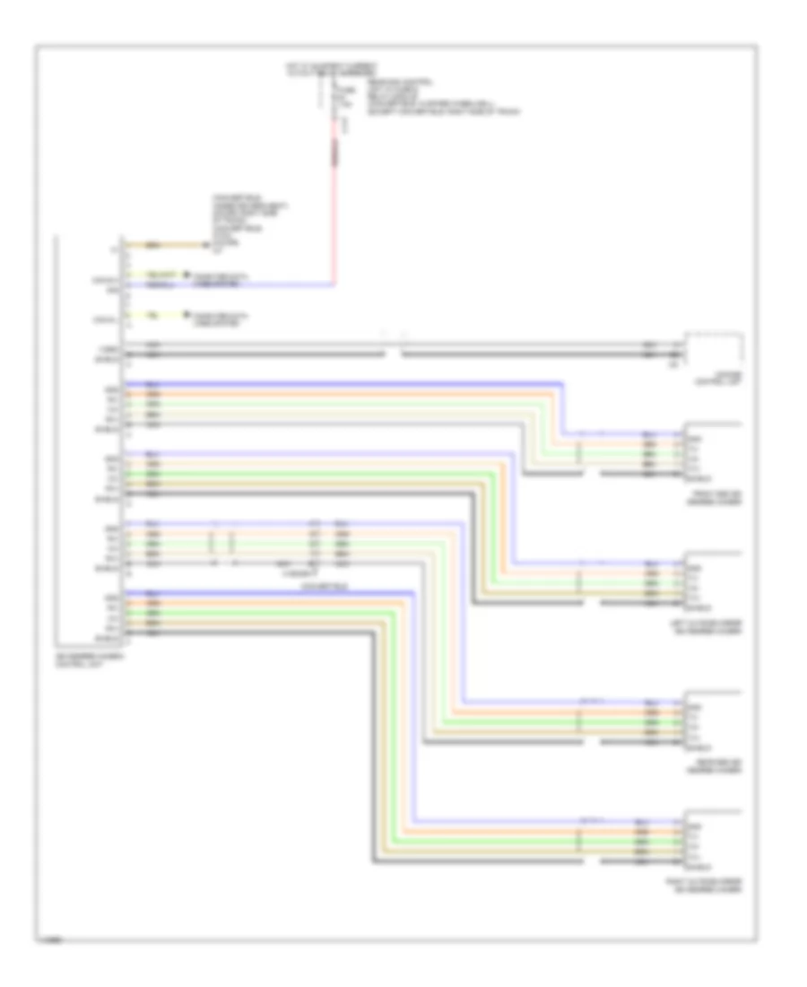
All Around Vision Camera Wiring Diagram, Sedan for Mercedes-Benz E350 2013
List of elements for All Around Vision Camera Wiring Diagram, Sedan for Mercedes-Benz E350 2013:
- (+)
- (-)
- (pins 1 to 10: not used)
- (pins 15 to 20: not used)
- (right side of trunk) w7/8
- 30g
- 360 degree camera control unit
- C11t
- Can e2 h
- Can e2 l
- Comand control unit
- Computer data lines system
- Front end 360 degree camera
- Fuse 5a
- Hot w/ quiescent current cutout relay energized
- Left outside mirror 360 degree camera
- Nca
- Rear end 360 degree camera
- Rear sam control unit w/ fuse & relay module (right side of trunk)
- Right outside mirror 360 degree camera
- Rx+
- Rx-
- Shield
- X26/38-c3
- X35/1-c7
- X35/2-c7
- X8/46-c5
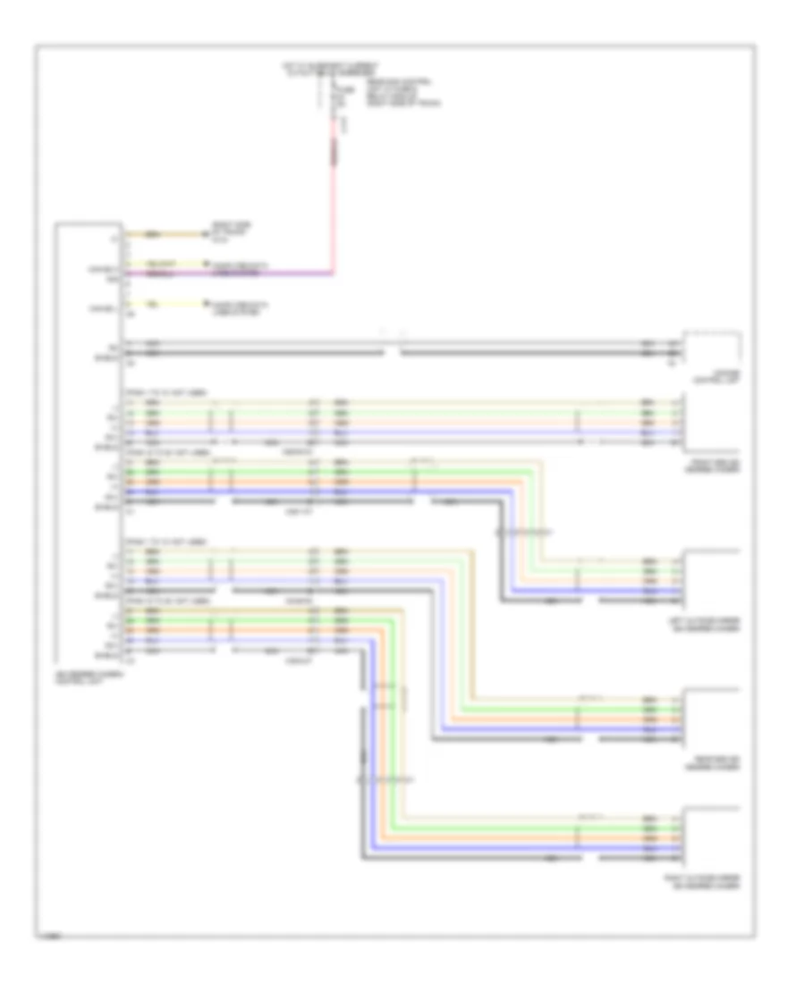
All Around Vision Camera Wiring Diagram, Wagon for Mercedes-Benz E350 2013
List of elements for All Around Vision Camera Wiring Diagram, Wagon for Mercedes-Benz E350 2013:
- (+)
- (-)
- (pins 1 to 10: not used)
- (pins 15 to 20: not used)
- (right side of trunk) w7/8
- 30g
- 360 degree camera control unit
- C11t
- Can e2 h
- Can e2 l
- Comand control unit
- Computer data lines system
- Front end 360 degree camera
- Fuse 5a
- Hot w/ quiescent current cutout relay energized
- Left outside mirror 360 degree camera
- Nca
- Rear end 360 degree camera
- Rear sam control unit w/ fuse & relay module (right side of trunk)
- Right outside mirror 360 degree camera
- Rx+
- Rx-
- Shield
- X26/38-c3
- X35/1-c7
- X35/2-c7
- X8/46-c5
Blind Spot Information System Wiring Diagram, Convertible for Mercedes-Benz E350 2013
List of elements for Blind Spot Information System Wiring Diagram, Convertible for Mercedes-Benz E350 2013:
- (if equipped) left blind spot assist readiness & warning indicator
- (if equipped) right blind spot assist readiness & warning indicator
- C12i
- C22i
- Can e1 h can g h
- Can g h
- Can g h can e1 h
- Can g l
- Can g l can e1 l
- Can-b h
- Can-b l
- Computer data lines system
- Early production
- Front sam control module w/ fuse/ relay module (left rear of engine compt)
- Fuse 5a
- Hot w/ circuit 15 relay energized
- Late production
- Led
- Led 31
- Left front door control unit
- Left outside mirror
- Left rear bumper intelligent radar sensor (behind left side of rear bumper)
- Nca
- Pnk
- Rear sam control module w/ fuse/relay module (convertible: in spare wheelwell) (coupe: right side of trunk)
- Right front door control unit
- Right outside mirror
- Right rear bumper intelligent radar sensor (behind right side of rear bumper)
- W7 (right side of trunk)
- X35/28
Blind Spot Information System Wiring Diagram, Coupe for Mercedes-Benz E350 2013
List of elements for Blind Spot Information System Wiring Diagram, Coupe for Mercedes-Benz E350 2013:
- (if equipped) left blind spot assist readiness & warning indicator
- (if equipped) right blind spot assist readiness & warning indicator
- C12i
- C22i
- Can e1 h can g h
- Can g h
- Can g h can e1 h
- Can g l
- Can g l can e1 l
- Can-b h
- Can-b l
- Computer data lines system
- Early production
- Front sam control module w/ fuse/ relay module (left rear of engine compt)
- Fuse 5a
- Hot w/ circuit 15 relay energized
- Late production
- Led
- Led 31
- Left front door control unit
- Left outside mirror
- Left rear bumper intelligent radar sensor (behind left side of rear bumper)
- Nca
- Pnk
- Rear sam control module w/ fuse/relay module (convertible: in spare wheelwell) (coupe: right side of trunk)
- Right front door control unit
- Right outside mirror
- Right rear bumper intelligent radar sensor (behind right side of rear bumper)
- W7 (right side of trunk)
- X35/28
Blind Spot Information System Wiring Diagram, Sedan for Mercedes-Benz E350 2013
List of elements for Blind Spot Information System Wiring Diagram, Sedan for Mercedes-Benz E350 2013:
- (if equipped) left blind spot assist readiness & warning indicator
- (if equipped) right blind spot assist readiness & warning indicator
- C12i
- C22i
- Can g h
- Can g l
- Can-b h
- Can-b l
- Computer data lines system
- Front sam control module w/ fuse/ relay module (left rear of engine compt)
- Fuse 7.5a
- Hot w/ circuit 15 relay energized
- Led
- Led 31
- Left front door control unit
- Left outside mirror
- Left rear bumper intelligent radar sensor (behind left side of rear bumper)
- Rear sam control module w/ fuse/relay module (right side of trunk)
- Red
- Right front door control unit
- Right outside mirror
- Right rear bumper intelligent radar sensor (behind right side of rear bumper)
- W7/8 (right side of trunk)
- X172/2
Blind Spot Information System Wiring Diagram, Wagon for Mercedes-Benz E350 2013
List of elements for Blind Spot Information System Wiring Diagram, Wagon for Mercedes-Benz E350 2013:
- (if equipped) left blind spot assist readiness & warning indicator
- (if equipped) right blind spot assist readiness & warning indicator
- C12i
- C22i
- Can g h
- Can g l
- Can-b h
- Can-b l
- Computer data lines system
- Front sam control module w/ fuse/ relay module (left rear of engine compt)
- Fuse 7.5a
- Hot w/ circuit 15 relay energized
- Led
- Led 31
- Left front door control unit
- Left outside mirror
- Left rear bumper intelligent radar sensor (behind left side of rear bumper)
- Rear sam control module w/ fuse/relay module (right side of trunk)
- Red
- Right front door control unit
- Right outside mirror
- Right rear bumper intelligent radar sensor (behind right side of rear bumper)
- W7/8 (right side of trunk)
- X172/2
COMAND Actuation Wiring Diagram, Convertible (1 of 3) for Mercedes-Benz E350 2013
List of elements for COMAND Actuation Wiring Diagram, Convertible (1 of 3) for Mercedes-Benz E350 2013:
- (+)
- (-)
- (center of trunk) (w/ teleaid emergency call system) emergency call system control unit
- (left front footwell) w15/5
- (not used)
- 30g
- Anst
- Aux gnd
- Aux jack electrical connector
- Aux l
- Aux r
- Aux shield
- C10t
- C2i
- Can a h
- Can a l
- Can b h
- Can b l
- Comand control unit
- Comand fan motor (left center of dash)
- Compensator/cellular telephone system umts
- Computer data lines system
- Data +
- Data -
- Diag
- Front sam control module w/ fuse/ relay module (left rear of engine compt)
- Fuse 20a
- Fuse 5a
- Gnd
- Hands-free system
- Hl+
- Hl-
- Hot w/ quiescent current cutout relay energized
- Hr+
- Hr-
- Inside rearview mirror
- Left door bass speaker
- Left door speaker (w/0 sound system)
- Left door tweeter
- Left rear bass speaker
- Left rear speaker (w/0 sound system)
- Left rear tweeter
- Lvds+
- Lvds-
- Mic +
- Mic -
- Mic 1+
- Mic 2+
- Microphone
- Mobile phone electrical connector
- Most data bus circuit
- Most in
- Most out
- Mute
- Nca
- On/off
- Pnk
- Radio w/ auto pilot system (w/ audio 50) radio (w/ audio 20)
- Red
- Res
- Right rear bass speaker
- Right rear speaker (w/0 sound system)
- Right rear tweeter
- Shield
- Tracer wire connector sleeve
- Usb
- Usb connector
- Vcc +5vc
- Vl+
- Vl-
- Vr+
- Vr-
- W/ audio 20
- W/ audio 20 & 50
- W/ audio 50
- W/ mobile phone preinstallation w/ universal interface
- W/ stationary heater
- W/ teleaid emergency call system
- W/o audio 20 & 50
- W18 (under driver's seat)
- Wake up
- X35/1-c1
- X39/45
COMAND Actuation Wiring Diagram, Convertible (2 of 3) for Mercedes-Benz E350 2013
List of elements for COMAND Actuation Wiring Diagram, Convertible (2 of 3) for Mercedes-Benz E350 2013:
- (left front footwell) w15/5
- (top of steering column) steering column module control unit
- 30g
- Accept/ terminate phone call button
- Audio/comand control panel
- Audio/comand controller
- Audio/comand display
- Back & voice control system off button
- Back button
- Buttons + & - setting of specific functions & volume control
- C11t
- C2i
- C5c
- Can a h
- Can a l
- Can-e l can-e1 l
- Can-e1 h can-e h
- Computer data lines system
- Delete button
- Early production
- Fanfare horns & air bag clock spring contact (top of steering column)
- Front sam control module w/ fuse/relay module (left rear of engine compt)
- Fuse 7.5a
- Gnd
- Hot w/ quiescent current cutout relay energized
- Late production
- Left multi-function steering wheel button group
- Lvds+
- Lvds-
- Mute
- Mute button
- Ok button
- Pnk
- Rear sam control module w/ fuse/ relay module (in spare wheelwell)
- Red
- Res
- Right door bass speaker
- Right door speaker (w/0 sound system)
- Right door tweeter
- Right multi-function steering wheel button group
- Scroll forward/ back button
- Steering wheel electronics (inside steering wheel)
- System selection button
- Tel
- Voice control system on button
- X35/2-c1
COMAND Actuation Wiring Diagram, Convertible (3 of 3) for Mercedes-Benz E350 2013
List of elements for COMAND Actuation Wiring Diagram, Convertible (3 of 3) for Mercedes-Benz E350 2013:
- (convertible) tv3, fm2 & dab band iii antenna amplifier (coupe) rear window antenna (fm) antenna amplifier
- (coupe: center front of trunk) (convertible: left front of trunk) global positioning system antenna splitter
- (pins: 1 to 12 not used)
- (right rear of roof) fm, am & cl (zv) antenna amplifier
- 30g
- Afm
- Amo
- Ant
- Ant bt
- Ant gps
- Comand control unit
- Convertible
- Coupe
- Digital audio broadcasting control unit (under center rear of trunk floor)
- Fm 2
- Fm1/am
- Fm1/fm
- Fm2
- Gnd
- Gps
- Most
- Most data bus circuit
- Most in
- Most out
- Navigation system
- Nca
- Rse
- Shield
- Telematics services communication module
- Tv antenna splitter (under right rear seat)
- Tv tuner (analog/digital) & digital tv tuner (if equipped) (convertible: in spare tire wheelwell) (coupe: right side of trunk)
- Tv1
- Tv2
- Tv2 & keyless go antenna amplifier (tv2 antenna amplifier: left rear of roof) (keyless go antenna amplifier: right rear of roof)
- Tv3
- Tv3 antenna amplifier (left "a" pillar)
- Tv3 antenna amplifier (right "a" pillar)
- Tv4
- V bus
- Vid
- W/ digital radio
- W/o digital radio
- W7 (right side of trunk)
- Wake up
- X1/23-tv
COMAND Actuation Wiring Diagram, Coupe (1 of 3) for Mercedes-Benz E350 2013
List of elements for COMAND Actuation Wiring Diagram, Coupe (1 of 3) for Mercedes-Benz E350 2013:
- (+)
- (-)
- (center of trunk) (w/ teleaid emergency call system) emergency call system control unit
- (left front footwell) w15/5
- (not used)
- 30g
- Anst
- Aux gnd
- Aux jack electrical connector
- Aux l
- Aux r
- Aux shield
- C10t
- C2i
- Can a h
- Can a l
- Can b h
- Can b l
- Comand control unit
- Comand fan motor (left center of dash)
- Compensator/cellular telephone system umts
- Computer data lines system
- Data +
- Data -
- Diag
- Front sam control module w/ fuse/ relay module (left rear of engine compt)
- Fuse 20a
- Fuse 5a
- Gnd
- Hands-free system
- Hl+
- Hl-
- Hot w/ quiescent current cutout relay energized
- Hr+
- Hr-
- Inside rearview mirror
- Left door bass speaker
- Left door speaker (w/0 sound system)
- Left door tweeter
- Left rear bass speaker
- Left rear speaker (w/0 sound system)
- Left rear tweeter
- Lvds+
- Lvds-
- Mic +
- Mic -
- Mic 1+
- Mic 2+
- Microphone
- Mobile phone electrical connector
- Most data bus circuit
- Most in
- Most out
- Mute
- Nca
- On/off
- Pnk
- Radio w/ auto pilot system (w/ audio 50) radio (w/ audio 20)
- Red
- Res
- Right rear bass speaker
- Right rear speaker (w/0 sound system)
- Right rear tweeter
- Shield
- Tracer wire connector sleeve
- Usb
- Usb connector
- Vcc +5vc
- Vl+
- Vl-
- Vr+
- Vr-
- W/ audio 20
- W/ audio 20 & 50
- W/ audio 50
- W/ mobile phone preinstallation w/ universal interface
- W/ stationary heater
- W/ teleaid emergency call system
- W/o audio 20 & 50
- W18 (under driver's seat)
- Wake up
- X35/1-c1
- X39/45
COMAND Actuation Wiring Diagram, Coupe (2 of 3) for Mercedes-Benz E350 2013
List of elements for COMAND Actuation Wiring Diagram, Coupe (2 of 3) for Mercedes-Benz E350 2013:
- (left front footwell) w15/5
- (top of steering column) steering column module control unit
- 30g
- Accept/ terminate phone call button
- Audio/comand control panel
- Audio/comand controller
- Audio/comand display
- Back & voice control system off button
- Back button
- Buttons + & - setting of specific functions & volume control
- C11t
- C2i
- C5c
- Can a h
- Can a l
- Can-e l can-e1 l
- Can-e1 h can-e h
- Computer data lines system
- Delete button
- Early production
- Fanfare horns & air bag clock spring contact (top of steering column)
- Front sam control module w/ fuse/relay module (left rear of engine compt)
- Fuse 7.5a
- Gnd
- Hot w/ quiescent current cutout relay energized
- Late production
- Left multi-function steering wheel button group
- Lvds+
- Lvds-
- Mute
- Mute button
- Ok button
- Pnk
- Rear sam control module w/ fuse/ relay module (in spare wheelwell)
- Red
- Res
- Right door bass speaker
- Right door speaker (w/0 sound system)
- Right door tweeter
- Right multi-function steering wheel button group
- Scroll forward/ back button
- Steering wheel electronics (inside steering wheel)
- System selection button
- Tel
- Voice control system on button
- X35/2-c1
COMAND Actuation Wiring Diagram, Coupe (3 of 3) for Mercedes-Benz E350 2013
List of elements for COMAND Actuation Wiring Diagram, Coupe (3 of 3) for Mercedes-Benz E350 2013:
- (convertible) tv3, fm2 & dab band iii antenna amplifier (coupe) rear window antenna (fm) antenna amplifier
- (coupe: center front of trunk) (convertible: left front of trunk) global positioning system antenna splitter
- (pins: 1 to 12 not used)
- (right rear of roof) fm, am & cl (zv) antenna amplifier
- 30g
- Afm
- Amo
- Ant
- Ant bt
- Ant gps
- Comand control unit
- Convertible
- Coupe
- Digital audio broadcasting control unit (under center rear of trunk floor)
- Fm 2
- Fm1/am
- Fm1/fm
- Fm2
- Gnd
- Gps
- Most
- Most data bus circuit
- Most in
- Most out
- Navigation system
- Nca
- Rse
- Shield
- Telematics services communication module
- Tv antenna splitter (under right rear seat)
- Tv tuner (analog/digital) & digital tv tuner (if equipped) (convertible: in spare tire wheelwell) (coupe: right side of trunk)
- Tv1
- Tv2
- Tv2 & keyless go antenna amplifier (tv2 antenna amplifier: left rear of roof) (keyless go antenna amplifier: right rear of roof)
- Tv3
- Tv3 antenna amplifier (left "a" pillar)
- Tv3 antenna amplifier (right "a" pillar)
- Tv4
- V bus
- Vid
- W/ digital radio
- W/o digital radio
- W7 (right side of trunk)
- Wake up
- X1/23-tv
COMAND Actuation Wiring Diagram, Sedan (1 of 3) for Mercedes-Benz E350 2013
List of elements for COMAND Actuation Wiring Diagram, Sedan (1 of 3) for Mercedes-Benz E350 2013:
- (+)
- (-)
- (center front of trunk) (w/ teleaid emergency call system) emergency call system control unit
- (if equipped) cellular telephone system antenna amplifier/ compensator
- (pins 1 to 8: not used)
- (under front passenger's seat) w19
- 30g
- Anst
- Aux jack electrical connector
- Aux1- gnd
- Aux1- l
- Aux1- s
- Aux1-r
- Aux2-gnd
- Aux2-l
- Aux2-r
- Aux2-s
- C10t
- Can a h
- Can a l
- Can b h
- Can b l
- Comand control unit
- Comand fan motor (left center of dash)
- Computer data lines system
- Diag
- Fl+
- Fl-
- Fr+
- Fr-
- Front sam control module w/ fuse/ relay module (left rear of engine compt)
- Fuse 20a
- Gnd
- Headphones electrical connector
- Hot w/ quiescent current cutout relay energized
- Keep on
- Left front door bass speaker
- Left front door tweeter
- Left rear door bass speaker
- Left rear door tweeter
- Media interface electrical connector (if equipped)
- Mic +
- Mic -
- Mic 1 +
- Mic 1+
- Mic 2 +
- Mic 2+
- Mobile phone electrical connector
- Most data bus circuit
- Most in
- Most out
- Mute
- Nca
- Pnk
- Radio (w/ audio 20) radio w/ auto pilot system (w/ audio 50)
- Right rear door bass speaker
- Right rear door tweeter
- Rl+
- Rl-
- Rr+
- Rr-
- Shield
- Sig
- Usb
- Usb bus
- Usb conncetor
- Usb+
- Usb-
- W/ audio 20
- W/ audio 20 & 50
- W/ audio 50
- W/o audio 20 & 50
- W/o sound system
- Wake up
- X115
- X18/35-c2
- X18/71
- X35/1-c1
- X35/3-c1
- X35/4-c1
COMAND Actuation Wiring Diagram, Sedan (2 of 3) for Mercedes-Benz E350 2013
List of elements for COMAND Actuation Wiring Diagram, Sedan (2 of 3) for Mercedes-Benz E350 2013:
- (center front of trunk) global positioning system antenna splitter
- (left "c" pillar) fm2 & dab antenna amplifier
- (not used)
- (right rear of roof) fm1, am, cl (zv) & keyless go antenna amplifier
- (top of steering column)
- +,-
- Accept/ terminate phone call button
- Back & voice control system off button
- Buttons + & - setting specific function & volume control
- Can-e1 l can-e l can-e h can-e1 h
- Computer data lines system
- Early production
- Fanfare horns & air bag clock spring contact (top of steering column)
- Gnd
- Hands-free system
- Inside rearview mirror
- Late production
- Left multi-function steering wheel button group
- Microphone
- Mute
- Mute button
- Nca
- Ok button
- Pnk
- R,rtn
- Red
- Right front door bass speaker
- Right front door tweeter
- Right multi-function steering wheel button group
- Scroll forward/ back button
- Sedan
- Steering column module control unit
- Steering wheel electronics (inside steering wheel)
- System selection button
- Tel
- U-mfl-r
- U-mll-l
- Voice control system on button
- W/o sound system
- Wagon
- X35/2-c1
- X8/46-c2
COMAND Actuation Wiring Diagram, Sedan (3 of 3) for Mercedes-Benz E350 2013
List of elements for COMAND Actuation Wiring Diagram, Sedan (3 of 3) for Mercedes-Benz E350 2013:
- (left front footwell) (w/o direct select) w15/5
- (under driver's seat)
- 30g
- 360 degree camera control unit (if equipped)
- Ant bt
- Ant gps
- Audio/comand control panel
- Audio/comand controller
- Audio/comand display
- Avi1 audio gnd
- Avi1 audio l
- Avi1 audio r
- Avi1 audio shd
- Avo3 audio gnd
- Avo3 audio l
- Avo3 audio r
- Avo3 audio shd
- Back button
- C5c
- Can a h
- Can a l
- Clock +
- Clock -
- Comand control unit
- Computer data lines system
- Data 0+
- Data 0-
- Data 1+
- Data 1-
- Data 2+
- Data 2-
- Delete button
- Dvd player (w/ rear entertainment)
- Early production
- Fm1/am
- Fm2
- Front sam control module w/ fuse/ relay module (left rear of engine compt)
- Fuse 7.5a
- Gnd
- Gps
- Hot w/ quiescent current cutout relay energized
- Late production
- Lvds +
- Lvds -
- Nca
- Night vision assist control unit (if equipped) (right kick panel)
- Red
- Res
- Rse1
- Rse2
- Shield
- Sig
- Video c
- Video c shd
- Video y
- Video y shd
- W/ direct select
- W18
- W19 (w/ direct select) (under front passenger's seat)
- X138/1-c1
- X18-c1
COMAND Actuation Wiring Diagram, Wagon (1 of 3) for Mercedes-Benz E350 2013
List of elements for COMAND Actuation Wiring Diagram, Wagon (1 of 3) for Mercedes-Benz E350 2013:
- (+)
- (-)
- (center front of trunk) (w/ teleaid emergency call system) emergency call system control unit
- (if equipped) cellular telephone system antenna amplifier/ compensator
- (pins 1 to 8: not used)
- (under front passenger's seat) w19
- 30g
- Anst
- Aux jack electrical connector
- Aux1- gnd
- Aux1- l
- Aux1- s
- Aux1-r
- Aux2-gnd
- Aux2-l
- Aux2-r
- Aux2-s
- C10t
- Can a h
- Can a l
- Can b h
- Can b l
- Comand control unit
- Comand fan motor (left center of dash)
- Computer data lines system
- Diag
- Fl+
- Fl-
- Fr+
- Fr-
- Front sam control module w/ fuse/ relay module (left rear of engine compt)
- Fuse 20a
- Gnd
- Headphones electrical connector
- Hot w/ quiescent current cutout relay energized
- Keep on
- Left front door bass speaker
- Left front door tweeter
- Left rear door bass speaker
- Left rear door tweeter
- Media interface electrical connector (if equipped)
- Mic +
- Mic -
- Mic 1 +
- Mic 1+
- Mic 2 +
- Mic 2+
- Mobile phone electrical connector
- Most data bus circuit
- Most in
- Most out
- Mute
- Nca
- Pnk
- Radio (w/ audio 20) radio w/ auto pilot system (w/ audio 50)
- Right rear door bass speaker
- Right rear door tweeter
- Rl+
- Rl-
- Rr+
- Rr-
- Shield
- Sig
- Usb
- Usb bus
- Usb conncetor
- Usb+
- Usb-
- W/ audio 20
- W/ audio 20 & 50
- W/ audio 50
- W/o audio 20 & 50
- W/o sound system
- Wake up
- X115
- X18/35-c2
- X18/71
- X35/1-c1
- X35/3-c1
- X35/4-c1
COMAND Actuation Wiring Diagram, Wagon (2 of 3) for Mercedes-Benz E350 2013
List of elements for COMAND Actuation Wiring Diagram, Wagon (2 of 3) for Mercedes-Benz E350 2013:
- (center front of trunk) global positioning system antenna splitter
- (left "c" pillar) fm2 & dab antenna amplifier
- (not used)
- (right rear of roof) fm1, am, cl (zv) & keyless go antenna amplifier
- (top of steering column)
- +,-
- Accept/ terminate phone call button
- Back & voice control system off button
- Buttons + & - setting specific function & volume control
- Can-e1 l can-e l can-e h can-e1 h
- Computer data lines system
- Early production
- Fanfare horns & air bag clock spring contact (top of steering column)
- Gnd
- Hands-free system
- Inside rearview mirror
- Late production
- Left multi-function steering wheel button group
- Microphone
- Mute
- Mute button
- Nca
- Ok button
- Pnk
- R,rtn
- Red
- Right front door bass speaker
- Right front door tweeter
- Right multi-function steering wheel button group
- Scroll forward/ back button
- Sedan
- Steering column module control unit
- Steering wheel electronics (inside steering wheel)
- System selection button
- Tel
- U-mfl-r
- U-mll-l
- Voice control system on button
- W/o sound system
- Wagon
- X35/2-c1
- X8/46-c2
COMAND Actuation Wiring Diagram, Wagon (3 of 3) for Mercedes-Benz E350 2013
List of elements for COMAND Actuation Wiring Diagram, Wagon (3 of 3) for Mercedes-Benz E350 2013:
- (left front footwell) (w/o direct select) w15/5
- (under driver's seat)
- 30g
- 360 degree camera control unit (if equipped)
- Ant bt
- Ant gps
- Audio/comand control panel
- Audio/comand controller
- Audio/comand display
- Avi1 audio gnd
- Avi1 audio l
- Avi1 audio r
- Avi1 audio shd
- Avo3 audio gnd
- Avo3 audio l
- Avo3 audio r
- Avo3 audio shd
- Back button
- C5c
- Can a h
- Can a l
- Clock +
- Clock -
- Comand control unit
- Computer data lines system
- Data 0+
- Data 0-
- Data 1+
- Data 1-
- Data 2+
- Data 2-
- Delete button
- Dvd player (w/ rear entertainment)
- Early production
- Fm1/am
- Fm2
- Front sam control module w/ fuse/ relay module (left rear of engine compt)
- Fuse 7.5a
- Gnd
- Gps
- Hot w/ quiescent current cutout relay energized
- Late production
- Lvds +
- Lvds -
- Nca
- Night vision assist control unit (if equipped) (right kick panel)
- Red
- Res
- Rse1
- Rse2
- Shield
- Sig
- Video c
- Video c shd
- Video y
- Video y shd
- W/ direct select
- W18
- W19 (w/ direct select) (under front passenger's seat)
- X138/1-c1
- X18-c1
Emergency Call Wiring Diagram, Convertible for Mercedes-Benz E350 2013
List of elements for Emergency Call Wiring Diagram, Convertible for Mercedes-Benz E350 2013:
- (+)
- (-)
- (left side of trunk) (if equipped) sound system amplifier control unit
- 15r(1)
- Ant gps
- Ant not
- Breakdown assistance button
- C11t
- C19i
- Can-d h
- Can-d l
- Center instrument panel speaker
- Comand control unit (w/ comand & audio 20)
- Computer data lines system
- Convertible
- Coupe
- Crash
- Diagnostic connector (under left side of dash)
- Emergency call system antenna (convertible: between rear seat backs) (coupe: center of hatshelf)
- Emergency call system button
- Emergency call system control unit (center front of trunk)
- Front sam control module w/ fuse/relay module (left rear of engine compt)
- Fuse 7.5a
- Global positioning system antenna splitter (if equipped) (convertible: left front of trunk) (coupe: center front of trunk)
- Gps
- Hot at all times
- Hot w/ circuit 15r relay 1 energized
- Info
- Info led
- Interior lights system
- Keep on
- Lct
- Mb-info & breakdown assistance button
- Mb-info button
- Mikr +
- Mikr -
- Multi-function antenna
- Mute
- Nca
- Nca s
- Not
- Overhead control panel electronics
- Rear sam control module w/ fuse/relay module (convertible: in spare wheelwell) (coupe: right side of trunk)
- Shield
- Sig
- Sos
- Sos led
- Tel
- W/ comand
- W/ comand & audio 20
- W/ navigation
- W/o comand & audio 20
- W/o navigation
- W18/3 (under driver's seat)
- Ws led
- X1-gps
- X18-c1
- X18/37
Emergency Call Wiring Diagram, Coupe for Mercedes-Benz E350 2013
List of elements for Emergency Call Wiring Diagram, Coupe for Mercedes-Benz E350 2013:
- (+)
- (-)
- (left side of trunk) (if equipped) sound system amplifier control unit
- 15r(1)
- Ant gps
- Ant not
- Breakdown assistance button
- C11t
- C19i
- Can-d h
- Can-d l
- Center instrument panel speaker
- Comand control unit (w/ comand & audio 20)
- Computer data lines system
- Convertible
- Coupe
- Crash
- Diagnostic connector (under left side of dash)
- Emergency call system antenna (convertible: between rear seat backs) (coupe: center of hatshelf)
- Emergency call system button
- Emergency call system control unit (center front of trunk)
- Front sam control module w/ fuse/relay module (left rear of engine compt)
- Fuse 7.5a
- Global positioning system antenna splitter (if equipped) (convertible: left front of trunk) (coupe: center front of trunk)
- Gps
- Hot at all times
- Hot w/ circuit 15r relay 1 energized
- Info
- Info led
- Interior lights system
- Keep on
- Lct
- Mb-info & breakdown assistance button
- Mb-info button
- Mikr +
- Mikr -
- Multi-function antenna
- Mute
- Nca
- Nca s
- Not
- Overhead control panel electronics
- Rear sam control module w/ fuse/relay module (convertible: in spare wheelwell) (coupe: right side of trunk)
- Shield
- Sig
- Sos
- Sos led
- Tel
- W/ comand
- W/ comand & audio 20
- W/ navigation
- W/o comand & audio 20
- W/o navigation
- W18/3 (under driver's seat)
- Ws led
- X1-gps
- X18-c1
- X18/37
Emergency Call Wiring Diagram, Sedan for Mercedes-Benz E350 2013
List of elements for Emergency Call Wiring Diagram, Sedan for Mercedes-Benz E350 2013:
- (+)
- (-)
- (left side of trunk) sound system amplifier control unit
- 15r
- Ant gps
- Ant not
- Breakdown assistance button
- C1 s
- C11t
- C19i
- Can-d h
- Can-d l
- Center instrument panel speaker
- Comand control unit (if equipped)
- Computer data lines system
- Crash
- Diagnostic connector (under left side of dash)
- Emergency call system antenna (center of hatshelf)
- Emergency call system button
- Emergency call system control unit (center front of trunk)
- Front sam control module w/ fuse/relay module (left rear of engine compt)
- Fuse 7.5a
- Global positioning system antenna splitter (center front of trunk)
- Gps
- Hot at all times
- Hot w/ circuit 15r relay 1 energized
- Info
- Info led
- Interior lights system
- Lct
- Mb-info & breakdown assistance button
- Mb-info button
- Mic (+)
- Mic (-)
- Mobile phone electrical connector (if equipped)
- Multi-function antenna
- Mute
- Nca
- Nca s
- Nca x
- Not
- Overhead control panel control module (w/ power tilting/ sliding roof) overhead control panel electronics (w/o power tilting/ sliding roof)
- Rear sam control module w/ fuse/relay module (right side of trunk)
- Shield
- Sig
- Sos
- Sos led
- Tel
- W/ advanced sound system
- W/ comand
- W/o advanced sound system
- W/o comand
- W6 (left side of trunk)
- Ws led
- X1-gps
- X18-c2
- X18/37-c1
Emergency Call Wiring Diagram, Wagon for Mercedes-Benz E350 2013
List of elements for Emergency Call Wiring Diagram, Wagon for Mercedes-Benz E350 2013:
- (+)
- (-)
- (left side of trunk) sound system amplifier control unit
- 15r
- Ant gps
- Ant not
- Breakdown assistance button
- C1 s
- C11t
- C19i
- Can-d h
- Can-d l
- Center instrument panel speaker
- Comand control unit (if equipped)
- Computer data lines system
- Crash
- Diagnostic connector (under left side of dash)
- Emergency call system antenna (center of hatshelf)
- Emergency call system button
- Emergency call system control unit (center front of trunk)
- Front sam control module w/ fuse/relay module (left rear of engine compt)
- Fuse 7.5a
- Global positioning system antenna splitter (center front of trunk)
- Gps
- Hot at all times
- Hot w/ circuit 15r relay 1 energized
- Info
- Info led
- Interior lights system
- Lct
- Mb-info & breakdown assistance button
- Mb-info button
- Mic (+)
- Mic (-)
- Mobile phone electrical connector (if equipped)
- Multi-function antenna
- Mute
- Nca
- Nca s
- Nca x
- Not
- Overhead control panel control module (w/ power tilting/ sliding roof) overhead control panel electronics (w/o power tilting/ sliding roof)
- Rear sam control module w/ fuse/relay module (right side of trunk)
- Shield
- Sig
- Sos
- Sos led
- Tel
- W/ advanced sound system
- W/ comand
- W/o advanced sound system
- W/o comand
- W6 (left side of trunk)
- Ws led
- X1-gps
- X18-c2
- X18/37-c1
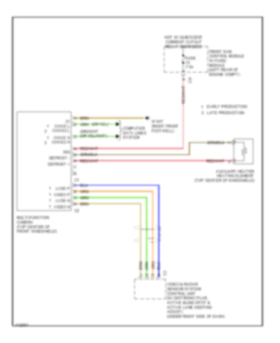
Multifunction Camera Wiring Diagram, Convertible for Mercedes-Benz E350 2013
List of elements for Multifunction Camera Wiring Diagram, Convertible for Mercedes-Benz E350 2013:
- 30g
- Auxiliary heater heating element (top center of windshield)
- C2i
- Can e h can e2 h
- Can e l can e2 l
- Computer data lines system
- Defrost +
- Defrost -
- Early production
- Front sam control module w/ fuse/ module (left rear of engine compt)
- Fuse 7.5a
- Hot w/ quiescent current cutout relay energized
- Late production
- Lvds n
- Lvds p
- Multi-function camera (top center of front windshield)
- Video & radar sensor system control unit (w/ distronic plus, active blind spot & active lane keeping assist) (under right side of dash)
- Video n
- Video p
- W15/7 (right front footwell)
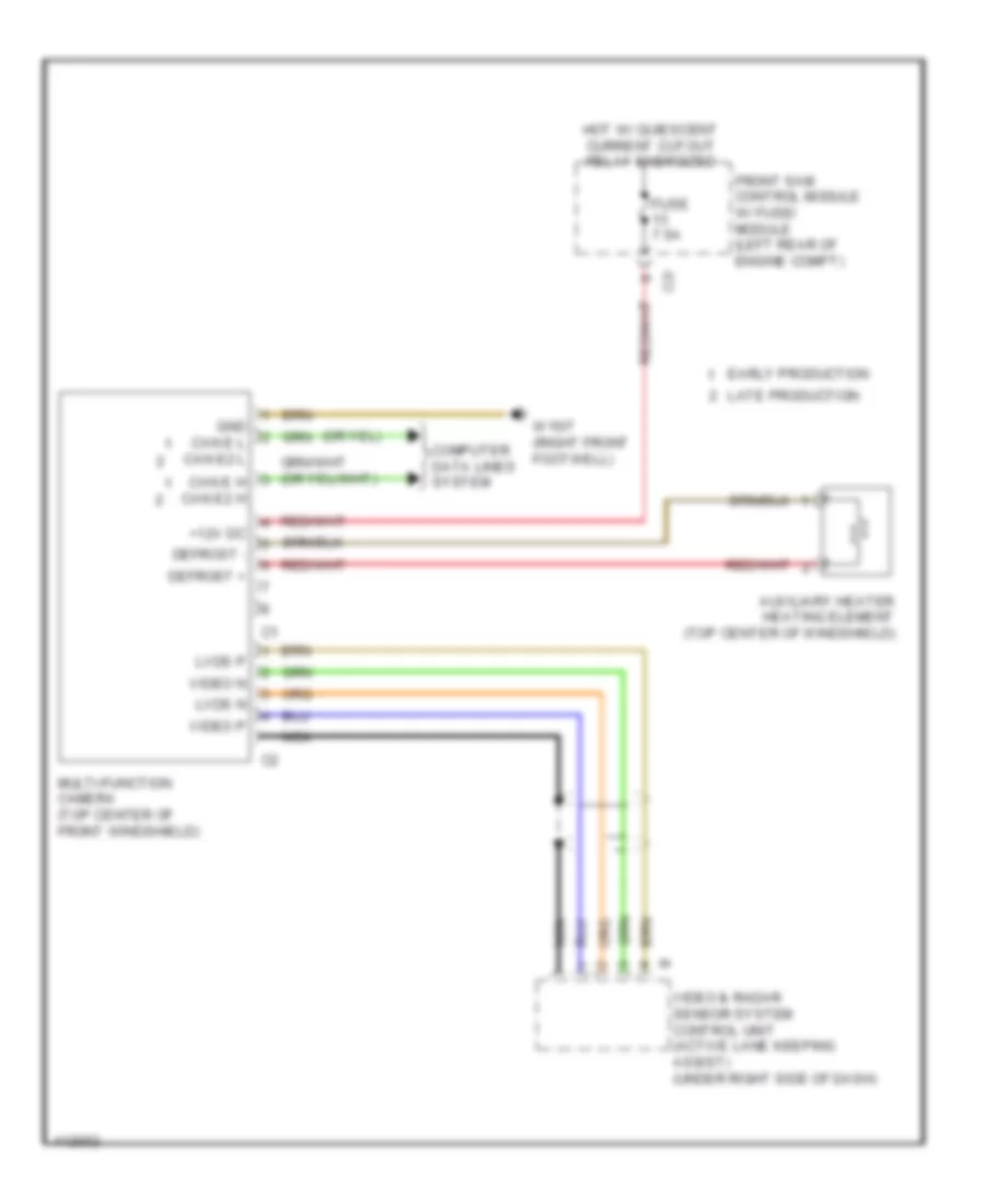
Multifunction Camera Wiring Diagram, Coupe for Mercedes-Benz E350 2013
List of elements for Multifunction Camera Wiring Diagram, Coupe for Mercedes-Benz E350 2013:
- 30g
- Auxiliary heater heating element (top center of windshield)
- C2i
- Can e h can e2 h
- Can e l can e2 l
- Computer data lines system
- Defrost +
- Defrost -
- Early production
- Front sam control module w/ fuse/ module (left rear of engine compt)
- Fuse 7.5a
- Hot w/ quiescent current cutout relay energized
- Late production
- Lvds n
- Lvds p
- Multi-function camera (top center of front windshield)
- Video & radar sensor system control unit (w/ distronic plus, active blind spot & active lane keeping assist) (under right side of dash)
- Video n
- Video p
- W15/7 (right front footwell)
Multifunction Camera Wiring Diagram, Sedan for Mercedes-Benz E350 2013
List of elements for Multifunction Camera Wiring Diagram, Sedan for Mercedes-Benz E350 2013:
- +12v dc
- Auxiliary heater heating element (top center of windshield)
- C2i
- Can e h can e2 h
- Can e l can e2 l
- Computer data lines system
- Defrost +
- Defrost -
- Early production
- Front sam control module w/ fuse/ module (left rear of engine compt)
- Fuse 7.5a
- Gnd
- Hot w/ quiescent current cutout relay energized
- Late production
- Lvds n
- Lvds p
- Multi-function camera (top center of front windshield)
- Nca
- Video & radar sensor system control unit (active lane keeping assist) (under right side of dash)
- Video n
- Video p
- W15/7 (right front footwell)
Multifunction Camera Wiring Diagram, Wagon for Mercedes-Benz E350 2013
List of elements for Multifunction Camera Wiring Diagram, Wagon for Mercedes-Benz E350 2013:
- +12v dc
- Auxiliary heater heating element (top center of windshield)
- C2i
- Can e h can e2 h
- Can e l can e2 l
- Computer data lines system
- Defrost +
- Defrost -
- Early production
- Front sam control module w/ fuse/ module (left rear of engine compt)
- Fuse 7.5a
- Gnd
- Hot w/ quiescent current cutout relay energized
- Late production
- Lvds n
- Lvds p
- Multi-function camera (top center of front windshield)
- Nca
- Video & radar sensor system control unit (active lane keeping assist) (under right side of dash)
- Video n
- Video p
- W15/7 (right front footwell)
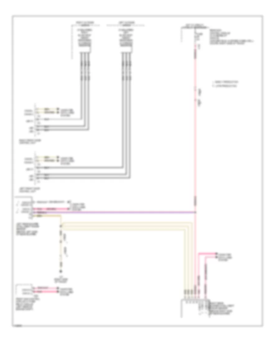
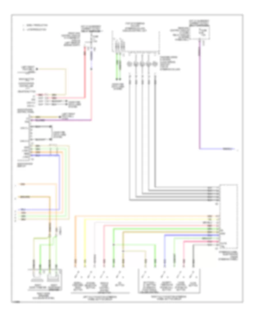
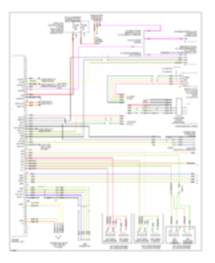
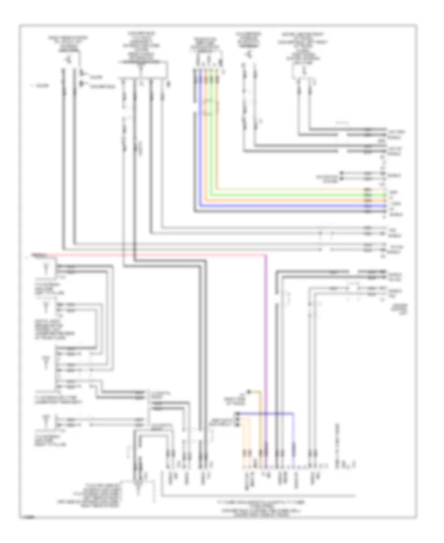
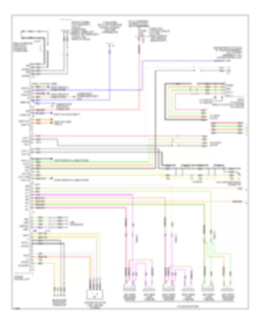
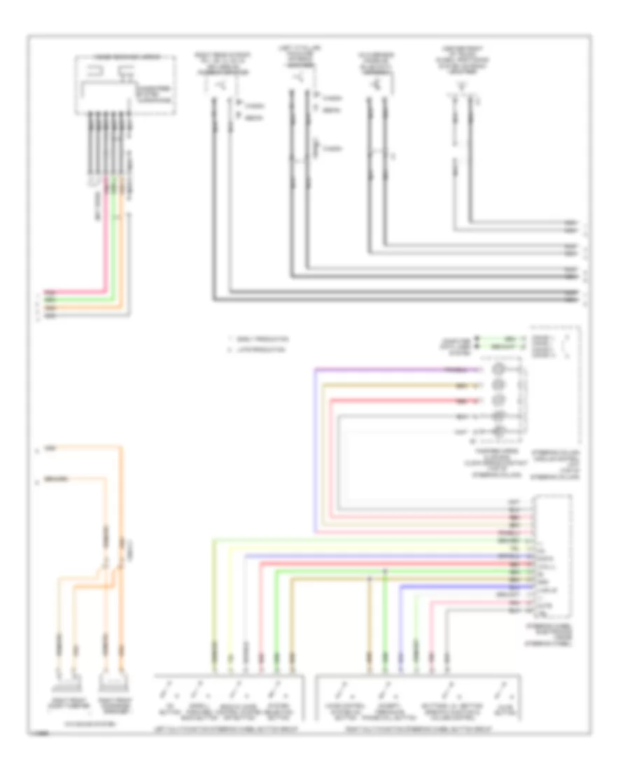
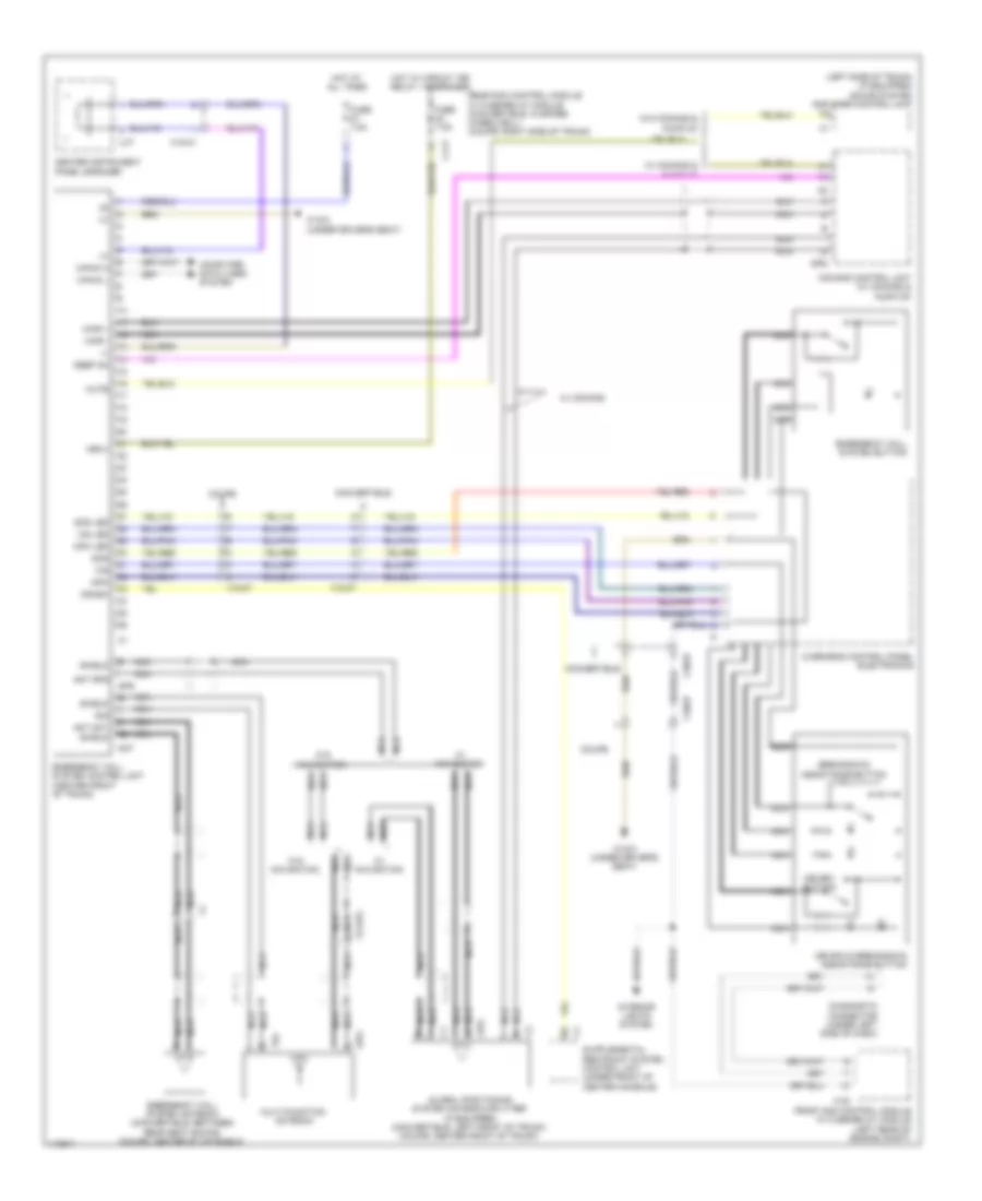
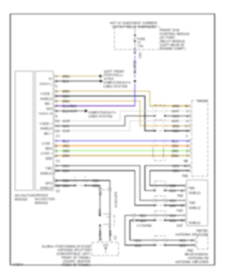
Navigation Wiring Diagram, Convertible for Mercedes-Benz E350 2013
List of elements for Navigation Wiring Diagram, Convertible for Mercedes-Benz E350 2013:
- (left front footwell) w15/5 computer data lines system
- 30g
- Ant
- C5c
- Can a h
- Can a l
- Computer data lines system
- Cradle navigation module
- Fm/tmc antenna splitter
- Fm2
- Front sam control module w/ fuse/ relay module (left rear of engine compt)
- Fuse 7.5a
- Global positioning system antenna splitter (convertible: left front of trunk) (coupe: center front of trunk)
- Gnd
- Gps
- Hot w/ quiescent current cutout relay energized
- Lvds +
- Lvds -
- Mic +
- Mic -
- Navigation module
- Nca
- Radio
- Rear window antenna fm antenna amplifier
- Res
- Shield
- Tmc
- Voice +
- Voice -
- X1/19-fm2
- X1/63-gps
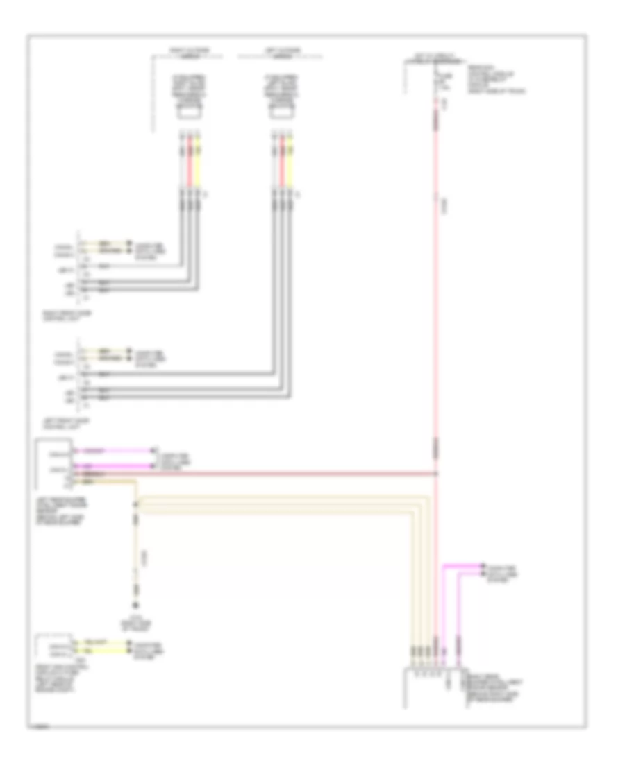
Navigation Wiring Diagram, Coupe for Mercedes-Benz E350 2013
List of elements for Navigation Wiring Diagram, Coupe for Mercedes-Benz E350 2013:
- (left front footwell) w15/5 computer data lines system
- 30g
- Ant
- C5c
- Can a h
- Can a l
- Computer data lines system
- Cradle navigation module
- Fm/tmc antenna splitter
- Fm2
- Front sam control module w/ fuse/ relay module (left rear of engine compt)
- Fuse 7.5a
- Global positioning system antenna splitter (convertible: left front of trunk) (coupe: center front of trunk)
- Gnd
- Gps
- Hot w/ quiescent current cutout relay energized
- Lvds +
- Lvds -
- Mic +
- Mic -
- Navigation module
- Nca
- Radio
- Rear window antenna fm antenna amplifier
- Res
- Shield
- Tmc
- Voice +
- Voice -
- X1/19-fm2
- X1/63-gps
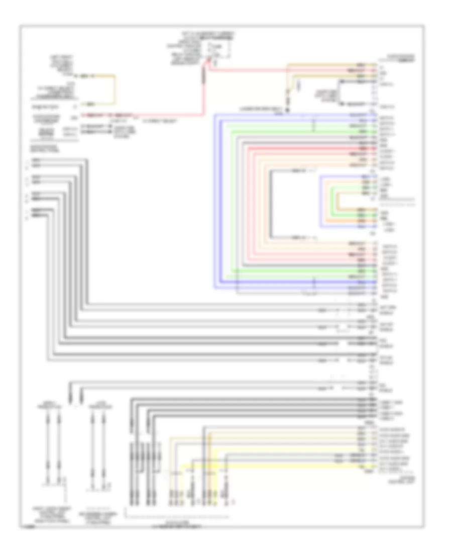
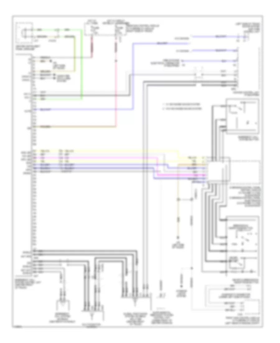
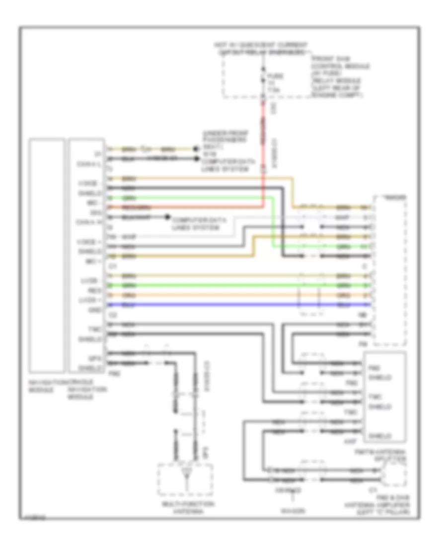
Navigation Wiring Diagram, Sedan for Mercedes-Benz E350 2013
List of elements for Navigation Wiring Diagram, Sedan for Mercedes-Benz E350 2013:
- (under front passengers seat) w19 computer data lines system
- 30g
- Ant
- C5c
- Can a h
- Can a l
- Computer data lines system
- Cradle navigation module
- Fm/tm antenna splitter
- Fm2
- Fm2 & dab antenna amplifier (left "c" pillar)
- Front sam control module w/ fuse/ relay module (left rear of engine compt)
- Fuse 7.5a
- Gnd
- Gps
- Hot w/ quiescent current cutout relay energized
- Lvds +
- Lvds -
- Mic +
- Mic -
- Multi-function antenna
- Navigation module
- Nca
- Radio
- Res
- Shield
- Tmc
- Voice +
- Voice -
- Wagon
- X18/35-c1
- X18/35-c3
- X8/46-c2
Navigation Wiring Diagram, Wagon for Mercedes-Benz E350 2013
List of elements for Navigation Wiring Diagram, Wagon for Mercedes-Benz E350 2013:
- (under front passengers seat) w19 computer data lines system
- 30g
- Ant
- C5c
- Can a h
- Can a l
- Computer data lines system
- Cradle navigation module
- Fm/tm antenna splitter
- Fm2
- Fm2 & dab antenna amplifier (left "c" pillar)
- Front sam control module w/ fuse/ relay module (left rear of engine compt)
- Fuse 7.5a
- Gnd
- Gps
- Hot w/ quiescent current cutout relay energized
- Lvds +
- Lvds -
- Mic +
- Mic -
- Multi-function antenna
- Navigation module
- Nca
- Radio
- Res
- Shield
- Tmc
- Voice +
- Voice -
- Wagon
- X18/35-c1
- X18/35-c3
- X8/46-c2
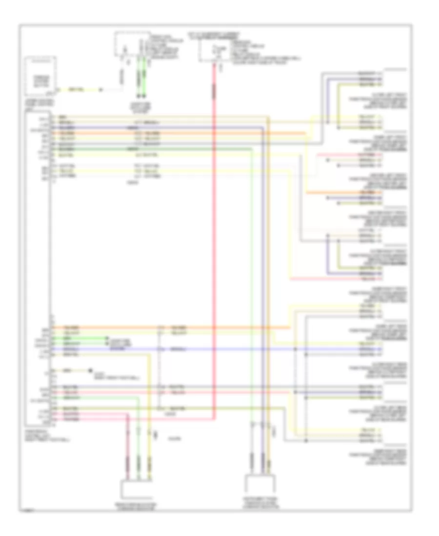
Parktronic Wiring Diagram, Early Production Convertible for Mercedes-Benz E350 2013
List of elements for Parktronic Wiring Diagram, Early Production Convertible for Mercedes-Benz E350 2013:
- (+) sh
- (+) sv
- (-) sh
- (-) sv
- 17c
- 30g
- C14i
- C19i
- Can e h
- Can e l
- Center left front parktronic distance sensor (behind center left side of front bumper)
- Center right front parktronic distance sensor (behind center right side of front bumper)
- Computer data lines system
- Coupe
- Front sam control module w/ fuse/ relay module (left rear of engine compt)
- Fuse 5a
- Hot w/ quiescent current cutout relay energized
- Inner left front parktronic distance sensor (behind inner left side of front bumper)
- Inner left rear parktronic distance sensor (behind inner left side of rear bumper)
- Inner right front parktronic distance sensor (behind inner right side of front bumper)
- Inner right rear parktronic distance sensor (behind inner right side of rear bumper)
- Instrument panel parking system warning indicator
- Lin 1
- Outer left front parktronic distance sensor (behind outer left side of front bumper)
- Outer left rear parktronic distance sensor (behind outer left side of rear bumper)
- Outer right front parktronic distance sensor (behind outer right side of front bumper)
- Outer right rear parktronic distance sensor (behind outer right side of rear bumper)
- Parking system button
- Parktronic control unit (right front footwell)
- Pnk/red
- Rear parking system warning indicator
- Rear sam control module w/ fuse/ relay module (convertible: in spare wheelwell) (coupe: right side of trunk)
- S10h
- S1v
- S2v
- S3v
- S4v
- S5v
- S6v
- S7h
- S8h
- S9h
- Upper control panel control unit
- W15/7 (right front footwell)
- Wh (+)
- Wh (-)
- Wh (data)
- Wv (+)
- Wv (-)
- Wv (data)
- X18-c1
- X18/2
- X26/38
- X35/28
Parktronic Wiring Diagram, Early Production Coupe for Mercedes-Benz E350 2013
List of elements for Parktronic Wiring Diagram, Early Production Coupe for Mercedes-Benz E350 2013:
- (+) sh
- (+) sv
- (-) sh
- (-) sv
- 17c
- 30g
- C14i
- C19i
- Can e h
- Can e l
- Center left front parktronic distance sensor (behind center left side of front bumper)
- Center right front parktronic distance sensor (behind center right side of front bumper)
- Computer data lines system
- Coupe
- Front sam control module w/ fuse/ relay module (left rear of engine compt)
- Fuse 5a
- Hot w/ quiescent current cutout relay energized
- Inner left front parktronic distance sensor (behind inner left side of front bumper)
- Inner left rear parktronic distance sensor (behind inner left side of rear bumper)
- Inner right front parktronic distance sensor (behind inner right side of front bumper)
- Inner right rear parktronic distance sensor (behind inner right side of rear bumper)
- Instrument panel parking system warning indicator
- Lin 1
- Outer left front parktronic distance sensor (behind outer left side of front bumper)
- Outer left rear parktronic distance sensor (behind outer left side of rear bumper)
- Outer right front parktronic distance sensor (behind outer right side of front bumper)
- Outer right rear parktronic distance sensor (behind outer right side of rear bumper)
- Parking system button
- Parktronic control unit (right front footwell)
- Pnk/red
- Rear parking system warning indicator
- Rear sam control module w/ fuse/ relay module (convertible: in spare wheelwell) (coupe: right side of trunk)
- S10h
- S1v
- S2v
- S3v
- S4v
- S5v
- S6v
- S7h
- S8h
- S9h
- Upper control panel control unit
- W15/7 (right front footwell)
- Wh (+)
- Wh (-)
- Wh (data)
- Wv (+)
- Wv (-)
- Wv (data)
- X18-c1
- X18/2
- X26/38
- X35/28
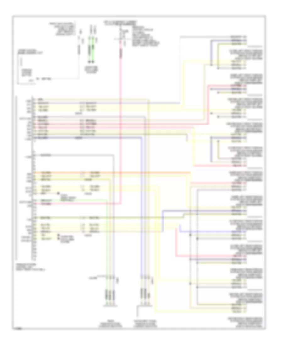
Parktronic Wiring Diagram, Late Production Convertible for Mercedes-Benz E350 2013
List of elements for Parktronic Wiring Diagram, Late Production Convertible for Mercedes-Benz E350 2013:
- + sh
- + we1
- + we2
- - sh
- - we1
- 30g
- C14i
- C17c
- C19i
- Can e h
- Can e l
- Can e2 h
- Can e2 l
- Center left front parking system distance sensor (behind center left side of front bumper)
- Center left rear parking system distance sensor (behind inner right side of rear bumper)
- Center right front parking system distance sensor (behind center right side of front bumper)
- Center right rear parking system distance sensor (behind inner right side of rear bumper)
- Computer data lines system
- Coupe
- Data we1
- Data we2
- Front sam control module w/ fuse & relay box (left rear of engine compt)
- Fuse 5a
- Hot w/ quiescent current cutout relay energized
- Inner left front parking system distance sensor (behind inner left side of front bumper)
- Inner left rear parking system distance sensor (behind inner left side of rear bumper)
- Inner right front parking system distance sensor (behind inner right side of front bumper)
- Inner right rear parking system distance sensor (behind inner right side of rear bumper)
- Instrument panel parking system warning indicator
- Lin 1
- Outer left front parking system distance sensor (behind outer left side of front bumper)
- Outer left rear parking system distance sensor (behind outer left side of rear bumper)
- Outer right front parking system distance sensor (behind outer right side of front bumper)
- Outer right rear parking system distance sensor (behind outer right side of rear bumper)
- Parking system button
- Parking system control unit (right front footwell)
- Pnk/red
- Rear parking system warning indicator
- Rear sam control module w/ fuse & relay module (convertible: in spare wheelwell) (except convertible: right side of trunk)
- S10h
- S11h
- S12h
- S1v
- S2v
- S3v
- S4v
- S5v
- S6v
- S7h
- S8h
- S9h
- Upper control panel control unit
- W15/7 (right front footwell)
- We2
- X18-c1
- X18/2
- X26/38
- X35/28
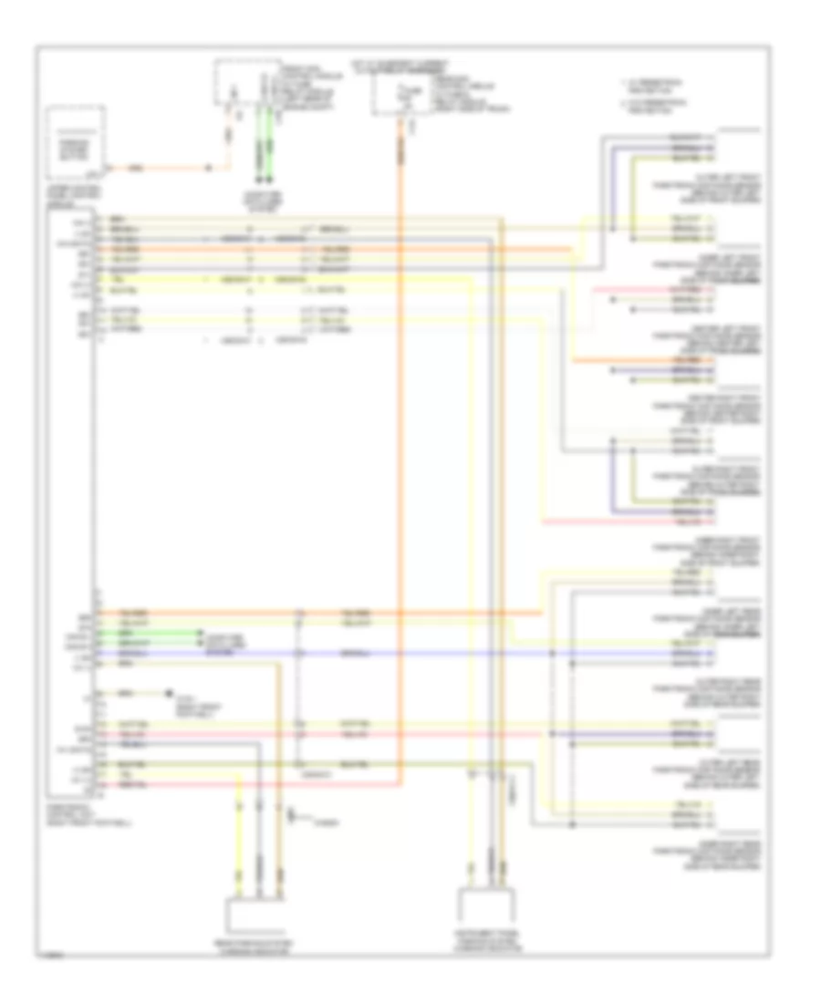
Parktronic Wiring Diagram, Late Production Coupe for Mercedes-Benz E350 2013
List of elements for Parktronic Wiring Diagram, Late Production Coupe for Mercedes-Benz E350 2013:
- + sh
- + we1
- + we2
- - sh
- - we1
- 30g
- C14i
- C17c
- C19i
- Can e h
- Can e l
- Can e2 h
- Can e2 l
- Center left front parking system distance sensor (behind center left side of front bumper)
- Center left rear parking system distance sensor (behind inner right side of rear bumper)
- Center right front parking system distance sensor (behind center right side of front bumper)
- Center right rear parking system distance sensor (behind inner right side of rear bumper)
- Computer data lines system
- Coupe
- Data we1
- Data we2
- Front sam control module w/ fuse & relay box (left rear of engine compt)
- Fuse 5a
- Hot w/ quiescent current cutout relay energized
- Inner left front parking system distance sensor (behind inner left side of front bumper)
- Inner left rear parking system distance sensor (behind inner left side of rear bumper)
- Inner right front parking system distance sensor (behind inner right side of front bumper)
- Inner right rear parking system distance sensor (behind inner right side of rear bumper)
- Instrument panel parking system warning indicator
- Lin 1
- Outer left front parking system distance sensor (behind outer left side of front bumper)
- Outer left rear parking system distance sensor (behind outer left side of rear bumper)
- Outer right front parking system distance sensor (behind outer right side of front bumper)
- Outer right rear parking system distance sensor (behind outer right side of rear bumper)
- Parking system button
- Parking system control unit (right front footwell)
- Pnk/red
- Rear parking system warning indicator
- Rear sam control module w/ fuse & relay module (convertible: in spare wheelwell) (except convertible: right side of trunk)
- S10h
- S11h
- S12h
- S1v
- S2v
- S3v
- S4v
- S5v
- S6v
- S7h
- S8h
- S9h
- Upper control panel control unit
- W15/7 (right front footwell)
- We2
- X18-c1
- X18/2
- X26/38
- X35/28
Parktronic Wiring Diagram, Sedan for Mercedes-Benz E350 2013
List of elements for Parktronic Wiring Diagram, Sedan for Mercedes-Benz E350 2013:
- (+) sh
- (+) sv
- (-) sh
- (-) sv
- 17c
- C14i
- C19i
- Can e h
- Can e l
- Center left front parktronic distance sensor (behind center left side of front bumper)
- Center right front parktronic distance sensor (behind center right side of front bumper)
- Computer data lines system
- Front sam control module w/ fuse/ relay module (left rear of engine compt)
- Fuse 5a
- Hot w/ quiescent current cutout relay energized
- Inner left front parktronic distance sensor (behind inner left side of front bumper)
- Inner left rear parktronic distance sensor (behind inner left side of rear bumper)
- Inner right front parktronic distance sensor (behind inner right side of front bumper)
- Inner right rear parktronic distance sensor (behind inner right side of rear bumper)
- Instrument panel parking system warning indicator
- Lin 1
- Outer left front parktronic distance sensor (behind outer left side of front bumper)
- Outer left rear parktronic distance sensor (behind outer left side of rear bumper)
- Outer right front parktronic distance sensor (behind outer right side of front bumper)
- Outer right rear parktronic distance sensor (behind outer right side of rear bumper)
- Parking system button
- Parktronic control unit (right front footwell)
- Protection
- Rear parking system warning indicator
- Rear sam control module w/ fuse & relay module (right side of trunk)
- S10h
- S1v
- S2v
- S3v
- S4v
- S5v
- S6v
- S7h
- S8h
- S9h
- Upper control panel control module
- W/ pedestrain protection
- W/o pedestrain
- W15/1 (right front footwell)
- Wagon
- Wh (+)
- Wh (-)
- Wh (data)
- Wv (+)
- Wv (-)
- Wv (data)
- X18/2
- X26/38-c1
- X26/38-c2
- X35/27-c1
- X35/28-c1
Parktronic Wiring Diagram, Wagon for Mercedes-Benz E350 2013
List of elements for Parktronic Wiring Diagram, Wagon for Mercedes-Benz E350 2013:
- (+) sh
- (+) sv
- (-) sh
- (-) sv
- 17c
- C14i
- C19i
- Can e h
- Can e l
- Center left front parktronic distance sensor (behind center left side of front bumper)
- Center right front parktronic distance sensor (behind center right side of front bumper)
- Computer data lines system
- Front sam control module w/ fuse/ relay module (left rear of engine compt)
- Fuse 5a
- Hot w/ quiescent current cutout relay energized
- Inner left front parktronic distance sensor (behind inner left side of front bumper)
- Inner left rear parktronic distance sensor (behind inner left side of rear bumper)
- Inner right front parktronic distance sensor (behind inner right side of front bumper)
- Inner right rear parktronic distance sensor (behind inner right side of rear bumper)
- Instrument panel parking system warning indicator
- Lin 1
- Outer left front parktronic distance sensor (behind outer left side of front bumper)
- Outer left rear parktronic distance sensor (behind outer left side of rear bumper)
- Outer right front parktronic distance sensor (behind outer right side of front bumper)
- Outer right rear parktronic distance sensor (behind outer right side of rear bumper)
- Parking system button
- Parktronic control unit (right front footwell)
- Protection
- Rear parking system warning indicator
- Rear sam control module w/ fuse & relay module (right side of trunk)
- S10h
- S1v
- S2v
- S3v
- S4v
- S5v
- S6v
- S7h
- S8h
- S9h
- Upper control panel control module
- W/ pedestrain protection
- W/o pedestrain
- W15/1 (right front footwell)
- Wagon
- Wh (+)
- Wh (-)
- Wh (data)
- Wv (+)
- Wv (-)
- Wv (data)
- X18/2
- X26/38-c1
- X26/38-c2
- X35/27-c1
- X35/28-c1
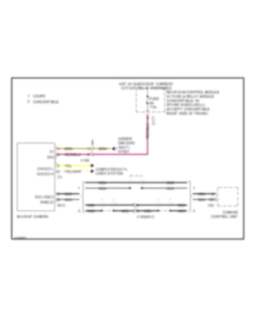
Rear Camera Wiring Diagram, Early Production Convertible for Mercedes-Benz E350 2013
List of elements for Rear Camera Wiring Diagram, Early Production Convertible for Mercedes-Benz E350 2013:
- 30g
- Backup camera (right side of trunk lid)
- C11t
- C5h
- Comand control unit
- Convertible
- Coupe
- Fuse 7.5a
- Gnd
- Hot w/ quiescent current cutout relay energized
- Nca
- Rear sam control module w/ fuse/relay module (convertible: in spare wheelwell) (coupe: right side of trunk)
- Red
- Rfl- r
- Vid
- Video gnd
- Video in
- Video out
- W18/3 (under driver's seat)
- X169
Rear Camera Wiring Diagram, Early Production Coupe for Mercedes-Benz E350 2013
List of elements for Rear Camera Wiring Diagram, Early Production Coupe for Mercedes-Benz E350 2013:
- 30g
- Backup camera (right side of trunk lid)
- C11t
- C5h
- Comand control unit
- Convertible
- Coupe
- Fuse 7.5a
- Gnd
- Hot w/ quiescent current cutout relay energized
- Nca
- Rear sam control module w/ fuse/relay module (convertible: in spare wheelwell) (coupe: right side of trunk)
- Red
- Rfl- r
- Vid
- Video gnd
- Video in
- Video out
- W18/3 (under driver's seat)
- X169
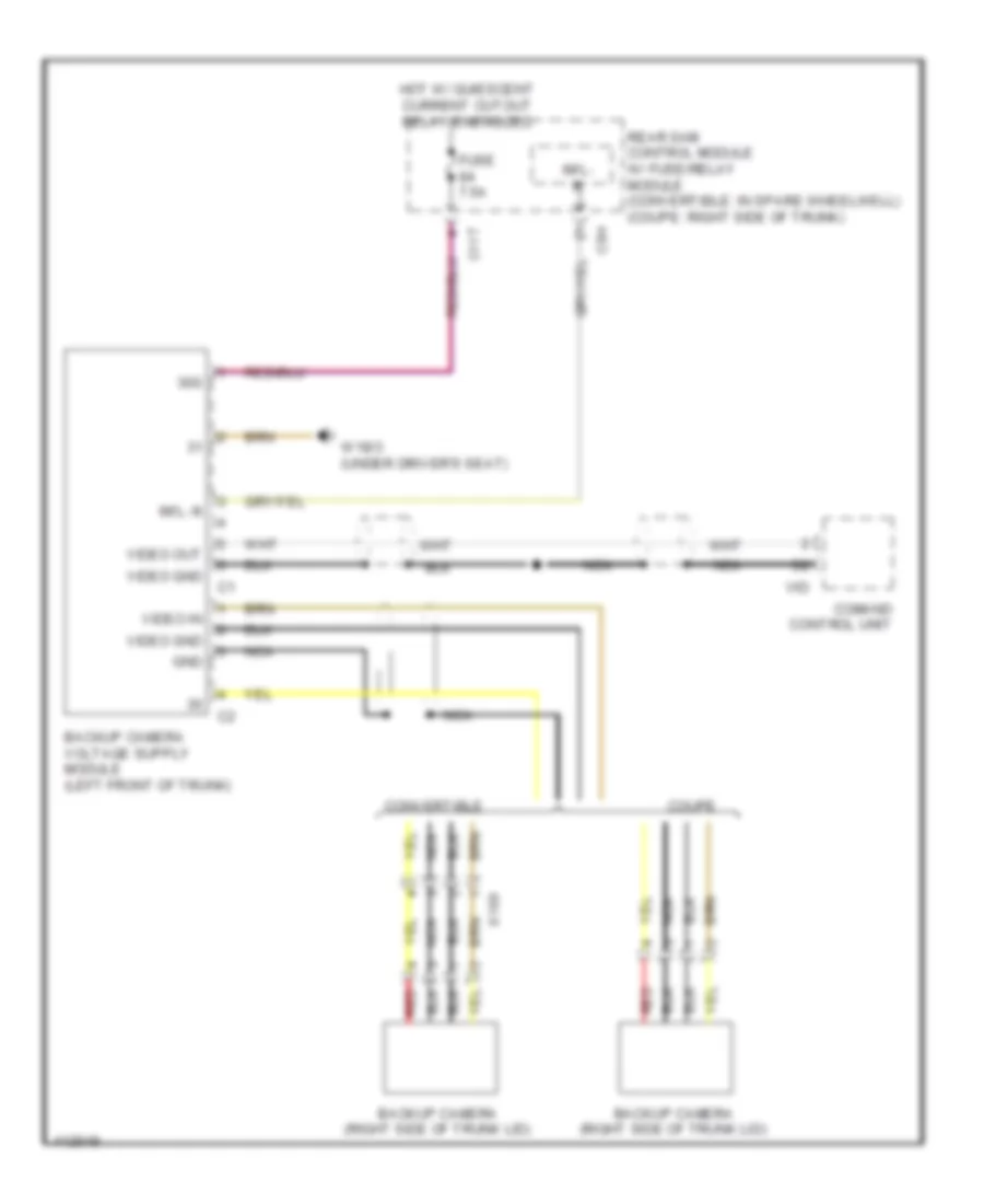
Rear Camera Wiring Diagram, Late Production Convertible for Mercedes-Benz E350 2013
List of elements for Rear Camera Wiring Diagram, Late Production Convertible for Mercedes-Benz E350 2013:
- (under driver's seat) w18/3
- 30g
- Backup camera
- C11t
- Can e2 h
- Can e2 l
- Comand control unit
- Computer data lines system
- Convertible
- Coupe
- Fuse 7.5a
- Hot w/ quiescent current cutout relay energized
- Nca
- Rear sam control module w/ fuse & relay module (convertible: in spare wheelwell) (except convertible: right side of trunk)
- Rvc
- Shield
- Sig video
- Vid
- X169
- X169-rvc
Rear Camera Wiring Diagram, Late Production Coupe for Mercedes-Benz E350 2013
List of elements for Rear Camera Wiring Diagram, Late Production Coupe for Mercedes-Benz E350 2013:
- (under driver's seat) w18/3
- 30g
- Backup camera
- C11t
- Can e2 h
- Can e2 l
- Comand control unit
- Computer data lines system
- Convertible
- Coupe
- Fuse 7.5a
- Hot w/ quiescent current cutout relay energized
- Nca
- Rear sam control module w/ fuse & relay module (convertible: in spare wheelwell) (except convertible: right side of trunk)
- Rvc
- Shield
- Sig video
- Vid
- X169
- X169-rvc
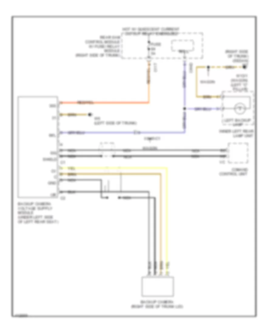
Rear Camera Wiring Diagram, Sedan for Mercedes-Benz E350 2013
List of elements for Rear Camera Wiring Diagram, Sedan for Mercedes-Benz E350 2013:
- (right side of trunk) (sedan) w7
- 30g
- Backup camera (right side of trunk lid)
- C11t
- C6hd
- Comand control unit
- Fuse 5a
- Gnd
- Hot w/ quiescent current cutout relay energized
- Inner left rear lamp unit
- Left backup lamp
- Nca
- Rear sam control module w/ fuse/ relay module (right side of trunk)
- Rfl
- Rfl-l
- Shield
- Sig
- W13/1 (wagon) (left "c" pillar)
- W6 (left side of trunk)
- Wagon
- X8/45-c1
Rear Camera Wiring Diagram, Wagon for Mercedes-Benz E350 2013
List of elements for Rear Camera Wiring Diagram, Wagon for Mercedes-Benz E350 2013:
- (right side of trunk) (sedan) w7
- 30g
- Backup camera (right side of trunk lid)
- C11t
- C6hd
- Comand control unit
- Fuse 5a
- Gnd
- Hot w/ quiescent current cutout relay energized
- Inner left rear lamp unit
- Left backup lamp
- Nca
- Rear sam control module w/ fuse/ relay module (right side of trunk)
- Rfl
- Rfl-l
- Shield
- Sig
- W13/1 (wagon) (left "c" pillar)
- W6 (left side of trunk)
- Wagon
- X8/45-c1
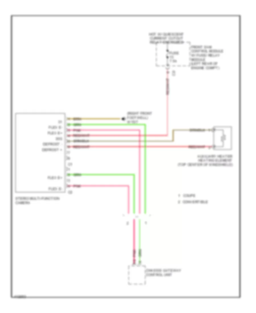
Stereo Multifunction Camera Wiring Diagram for Mercedes-Benz E350 2013
List of elements for Stereo Multifunction Camera Wiring Diagram for Mercedes-Benz E350 2013:
- (right front footwell) w15/7
- 30g
- Auxiliary heater heating element (top center of windshield)
- C2i
- Chassis gateway control unit
- Convertible
- Coupe
- Defrost +
- Defrost -
- Flex e+
- Flex e-
- Front sam control module w/ fuse/ relay module (left rear of engine compt)
- Fuse 7.5a
- Hot w/ quiescent current cutout relay energized
- Pnk
- Sterio multi-function camera

 Dansk
Dansk Deutsch
 Ελληνικά
 English
 English
 Español
 Suomi
Suomi Français
 Français
 עברית
עברית Hrvatski
 Magyar
 Italiano
 日本語
日本語 한국어
한국어 Nederlands
 Polski
 Português
 Português
 Română
 Русский
 Slovenčina
 Slovenščina
 Svenska
 Türkçe
 中文 (中国)