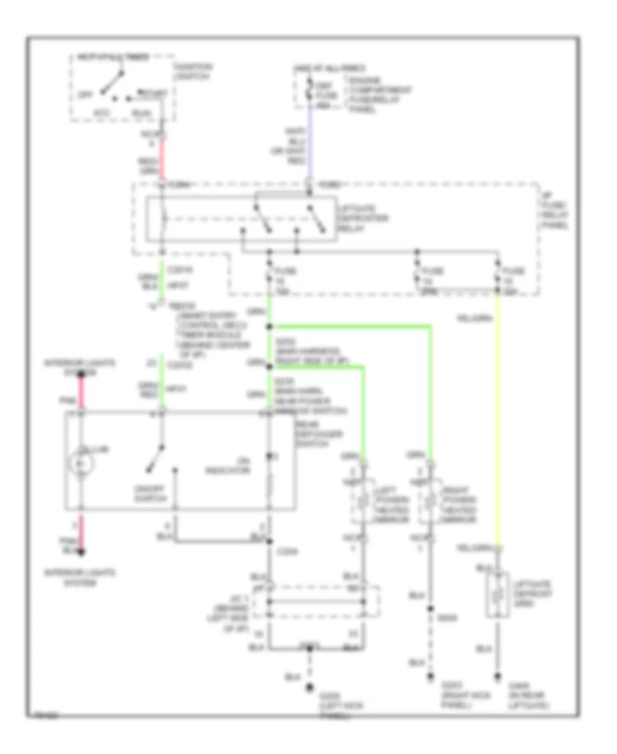
AUTOMOTIVE ELECTRICIANS PORTAL

DEFOGGERS – Mercury Villager Nautica 1997 – SYSTEM WIRING DIAGRAMS

DEFOGGERS

Defogger Wiring Diagram for Mercury Villager Nautica 1997

Defogger Wiring Diagram for Mercury Villager Nautica 1997 https://portal-diagnostov.com/license.html
https://portal-diagnostov.com/license.html Automotive Electricians Portal FZCO Automotive Electricians Portal FZCO
Få åtkomst till alla kopplingsscheman bilDownload PDF file

List of elements for Defogger Wiring Diagram for Mercury Villager Nautica 1997:

  • Acc
  • C2016
  • C202
  • C2030
  • C2032
  • C204
  • Def fuse 45a
  • Engine compartment fuse/relay panel
  • Fuse 10a
  • Fuse 20a
  • G200 (left kick panel)
  • G203 (right kick panel)
  • G406 (in rear liftgate)
  • Hf07
  • Hot at all times
  • I/p fuse/ relay panel
  • Ignition switch
  • Illum
  • Indicator
  • Interior lights system
  • J/c 1 (behind left side of i/p)
  • Left power/ heated mirror
  • Liftgate defrost grid
  • Liftgate defroster relay
  • Nca
  • Near power window switch)
  • Off
  • On/off switch
  • Pnk
  • Rear defogger switch
  • Right power/ heated mirror
  • Run
  • S203
  • S600
  • Smart entry control (sec)/ timer module (behind center of i/p)
  • Start