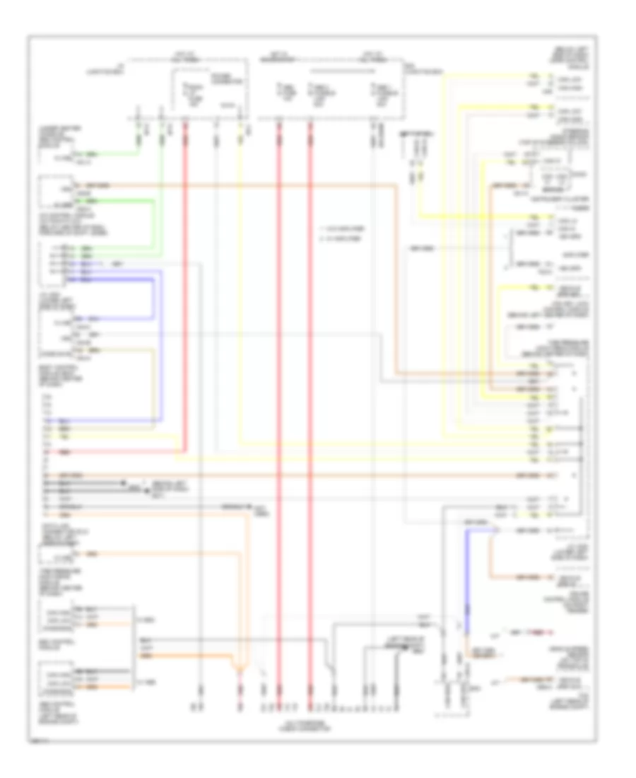
COMPUTER DATA LINES
Computer Data Lines Wiring Diagram for Hyundai Elantra GLS 2008
List of elements for Computer Data Lines Wiring Diagram for Hyundai Elantra GLS 2008:
- (behind left side of dash) gm11
- (below left side of dash) mdps control module
- (left rear of engine compt) ge23
- (not used)
- (under center console) srs control module
- A/c control module (automatic a/c) (below center of dash, forward of shift lever)
- A/t
- A01-a
- Abs 1 fusible link 40a
- Abs 2 fusible link 20a
- Abs control module (left rear of engine compt)
- Abs fuse 10a
- Amplifier
- Atm key lock control module (behind left center of dash)
- Audio
- Body control module (bcm) (behind center of dash)
- Can hi
- Can high
- Can ic
- Can lo
- Can low
- Cbg-a
- Cbg-k
- Code save
- Cruise control module (on right fender)
- Data link connector (dlc) (below left side of dash)
- Diagnosis
- E/r junction box
- E/r-erom
- Ecm
- Esc control module
- F23-a
- Gm21
- Hot at all times
- Hot in on or start
- I/p junction box
- I/p-c
- I/p-d
- I/p-e
- Instrument cluster
- J/c jm02 (lower left side of dash)
- J/c jm04 (lower left side of dash)
- K-line
- M/t
- M01-a
- M04-a
- M04-b
- M04-c
- M05-a
- M05-b
- M49
- Micom
- Multipurpose check connector
- Pnk
- Power connector
- Red
- Room lp fuse 15a
- Set top box
- Spd sig
- Steering angle sensor (top of steering column)
- Tcm (left rear of engine compt)
- Tire pressure monitoring module (behind center of dash)
- Veh spd
- Vehicle spd in
- Vehicle spd out
- Vehicle spd sig
- Vehicle speed sensor (on top of transaxle)
- Vss
- W/ abs
- W/ amplifier
- W/ esc
- W/o amplifier
 English