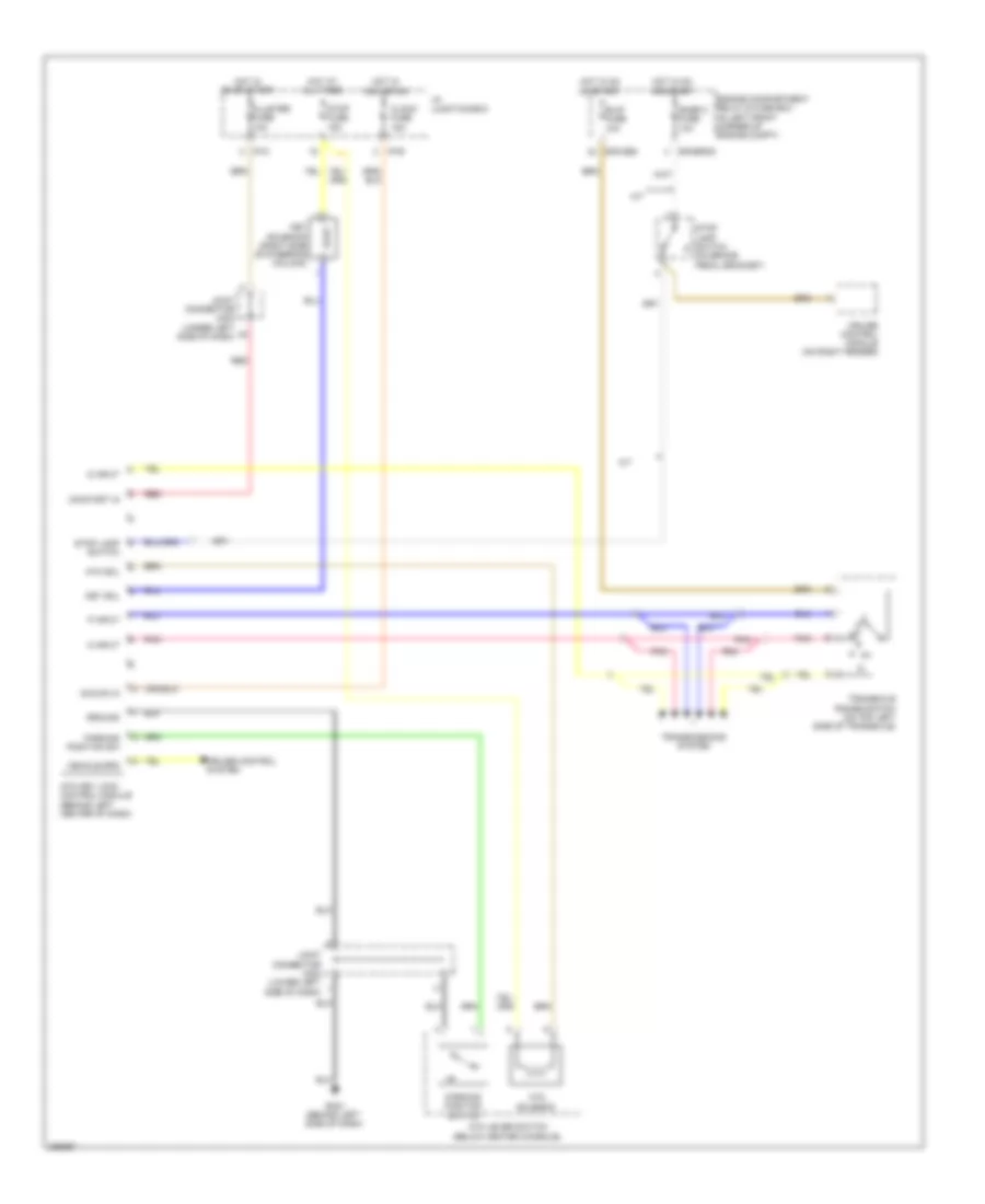
SHIFT INTERLOCK
Shift Interlock Wiring Diagram for Hyundai Elantra GLS 2008
List of elements for Shift Interlock Wiring Diagram for Hyundai Elantra GLS 2008:
- A/t
- Acc/on in
- Atm key lock control module (behind left center of dash)
- Atm lever switch (below center console)
- Atm sol
- Atm solenoid
- B/up fuse 10a
- Clock fuse 15a
- Cluster fuse 10a
- Cruise control module (on right fender)
- Cruise control system
- D input
- E/r-cbg
- E/r-erom
- Engine compartment relay & fuse box (in left front corner of engine compt)
- Gm21 (behind left side of dash)
- Ground
- Hot at all times
- Hot in acc or on
- Hot in on or start
- I/p junction box
- I/p-b
- I/p-c
- Joint connector jm03 (under left side of dash)
- Joint connector jm04 (lower left side of dash)
- Key sol
- Key solenoid (right side of steering column)
- N input
- On/start in
- P input
- Parking position sw
- Parking position switch
- Pnk
- Red
- Snsr 2 fuse 10a
- Stop fuse 15a
- Stop lamp switch
- Stop lamp switch (on brake pedal bracket)
- Transaxle range switch (on top left side of transaxle)
- Transmissions system
- Vehicle spd
 English