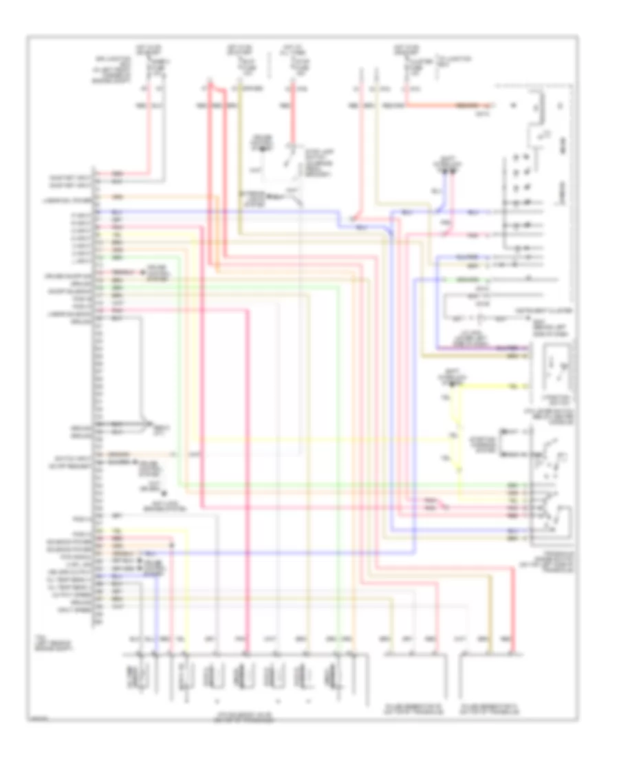
TRANSMISSION
Transmission Wiring Diagram for Hyundai Elantra GLS 2008
List of elements for Transmission Wiring Diagram for Hyundai Elantra GLS 2008:
- 2 input
- 2 or l sig
- 3 input
- 3 position switch
- 5v regulator
- Anti-lock brakes system
- Atm lever switch (below center console)
- Atm solenoid valve (on top of transaxle)
- B/up fuse 10a
- Cluster fuse 10a
- Cruise control system
- Cruise on/off sig
- D input
- E/r junction box (in left front corner of engine compt)
- E/r-cbg
- Exterior lights system
- Gbg12 (a/t)
- Gm21 (behind left
- Ground
- Hot at all times
- Hot in on or start
- I/p junction box
- I/p-b
- I/p-c
- I/p-d
- Input speed
- Instrument cluster
- J/c jm04 (lower left side of dash)
- L input
- Linear sol power
- Linear solenoid
- M01-a
- M01-b
- M01-c
- Micom
- N input
- Od & lr pcsv-a
- Od off request
- Oil temp sens (+)
- Oil temp sens (-)
- On/off solenoid
- On/start input
- Output speed
- P input
- Pcsv-a
- Pcsv-b
- Pcsv-b 24 brake
- Pcsv-c
- Pcsv-c ud
- Pcsv-d
- Pcsv-d dccsv
- Pnk
- Pulse generator "a" (on top of transaxle)
- Pulse generator "b" (on top of transaxle)
- Pwm sig
- Pwm signal
- R input
- Red
- Sensor oil temp
- Shift interlock system
- Side of dash)
- Snsr 2 fuse 10a
- Solenoid linear
- Solenoid power
- Starting/ charging system
- Stop fuse 15a
- Stop lamp switch (on brake pedal bracket)
- Switch input
- Tcm (left rear of engine compt)
- Transaxle range switch (on top left side of transaxle)
- Veh spd output
 English