ENGINE PERFORMANCE
1.6L
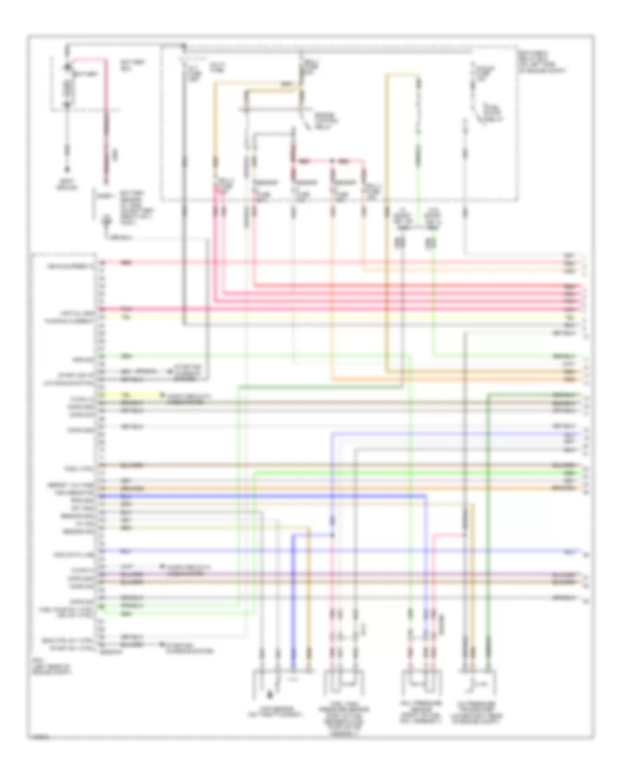
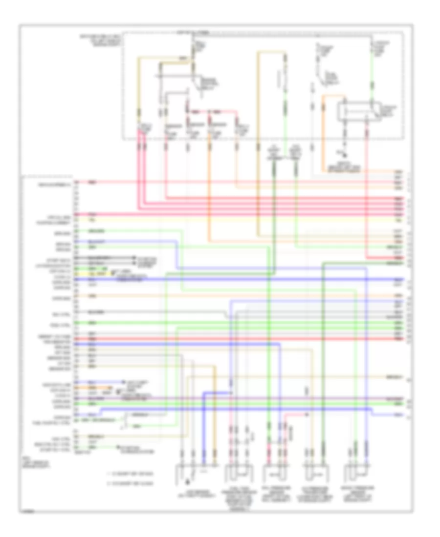
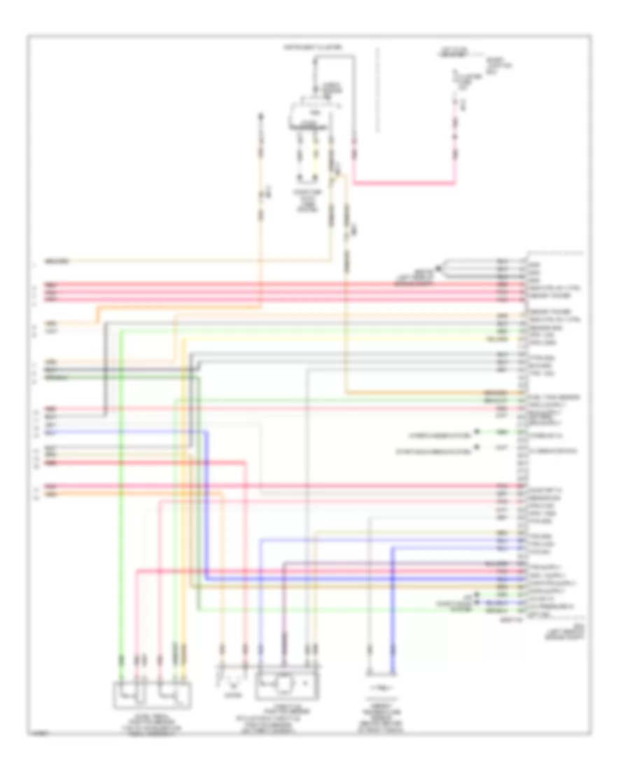
1.6L, Engine Performance Wiring Diagram, with DCT (1 of 5) for Hyundai Veloster 2014

List of elements for 1.6L, Engine Performance Wiring Diagram, with DCT (1 of 5) for Hyundai Veloster 2014:
- A/c pressure transducer (lower right rear of engine compt)
- Alt fuse 125a
- Ams fuse 10a
- Apt gnd
- Battery
- Battery box
- Body ground
- C-can hi
- C-can lo
- Ccp can hi
- Ccp can lo
- Ckps gnd
- Ckps sig
- Cmps gnd
- Cmps sig
- Computer data lines system
- E/r fuse & relay box (on left side of engine compt)
- Ecm (left rear of engine compt)
- Ecu 1 fuse 30a
- Ecu 2 fuse 15a
- Ecu 4 fuse 15a
- Ef11
- Eggd-mk
- Eggdinj
- Eng ctrl rly ctrl
- Engine control relay
- F/pump fuse 15a
- Fuel pump relay
- Fuel pump rly ctrl (or ccv ctrl)
- Fuel tank pressure sensor (part of fuel sender & fuel pump motor assembly)
- Iat sig
- Immo data line
- Lin communication
- Lin line
- Map sensor (on throttle body)
- Multi fuse
- Nernst voltage
- Pcsv ctrl
- Pnk
- Pumping current
- Rail pressure sensor (front of fuel rail assembly)
- Red
- Rps gnd
- Rps sig
- Sensor 1 fuse 20a
- Sensor 2 fuse 10a
- Sensor 3 fuse 15a
- Sensor gnd
- Sensor sig
- Snsr +
- Start rly ctrl
- Start sig in
- Starting/ charging system
- Trim resistor
- Vehicle speed in
- Virtual gnd
- W/ smart key & immo
- W/o smart key or immo
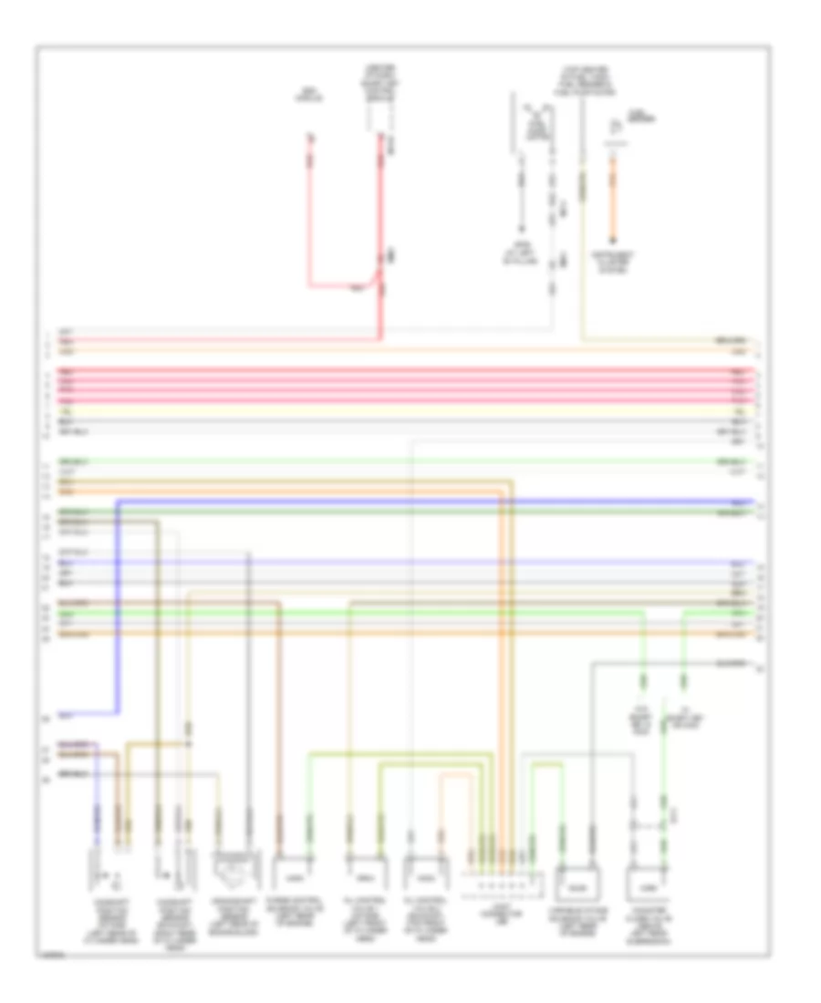
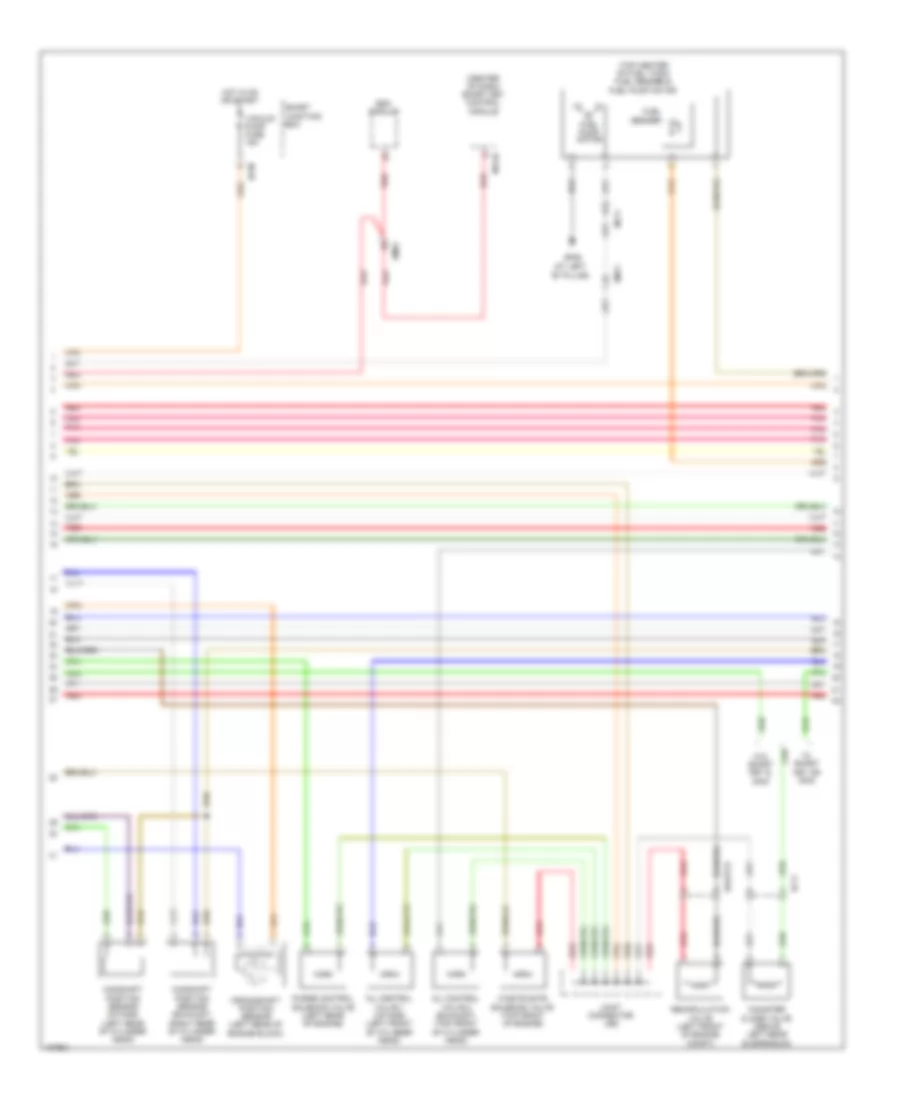
1.6L, Engine Performance Wiring Diagram, with DCT (2 of 5) for Hyundai Veloster 2014
List of elements for 1.6L, Engine Performance Wiring Diagram, with DCT (2 of 5) for Hyundai Veloster 2014:
- (center of dash) smart key control module
- (left front of cylinder head)
- (top center of fuel tank) fuel sender & fuel pump motor
- (top front of cylinder head)
- Camshaft position sensor (exhaust) (right rear of cylinder head)
- Camshaft position sensor (intake) (left rear of cylinder head)
- Canister close valve (above left rear suspension)
- Crankshaft position sensor (left rear of engine block)
- Ef11
- Em11
- Em61
- Esc module
- Fuel
- Fuel pump motor
- Gf06 (at left "b" pillar)
- Instrument cluster system
- Joint connector je01
- M13-b
- Mf11
- Oil control valve 1 (intake)
- Oil control valve 2 (exhaust)
- Pnk
- Purge control solenoid valve (left rear of engine)
- Red
- Sender
- Variable intake solenoid valve (left rear of engine)
- W/ smart key & immo
- W/o smart key or immo
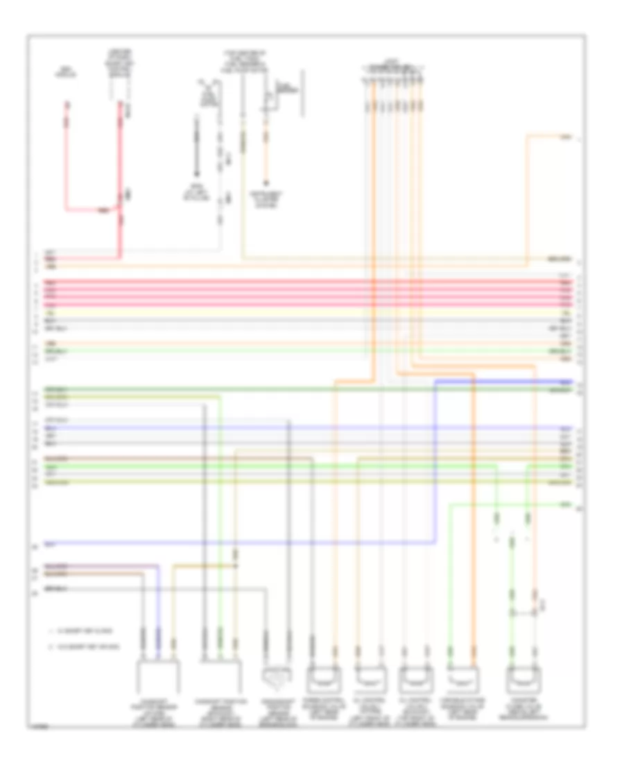
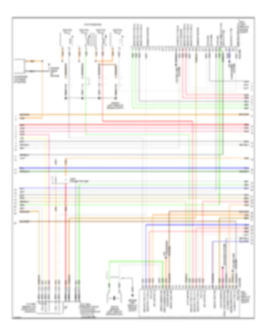
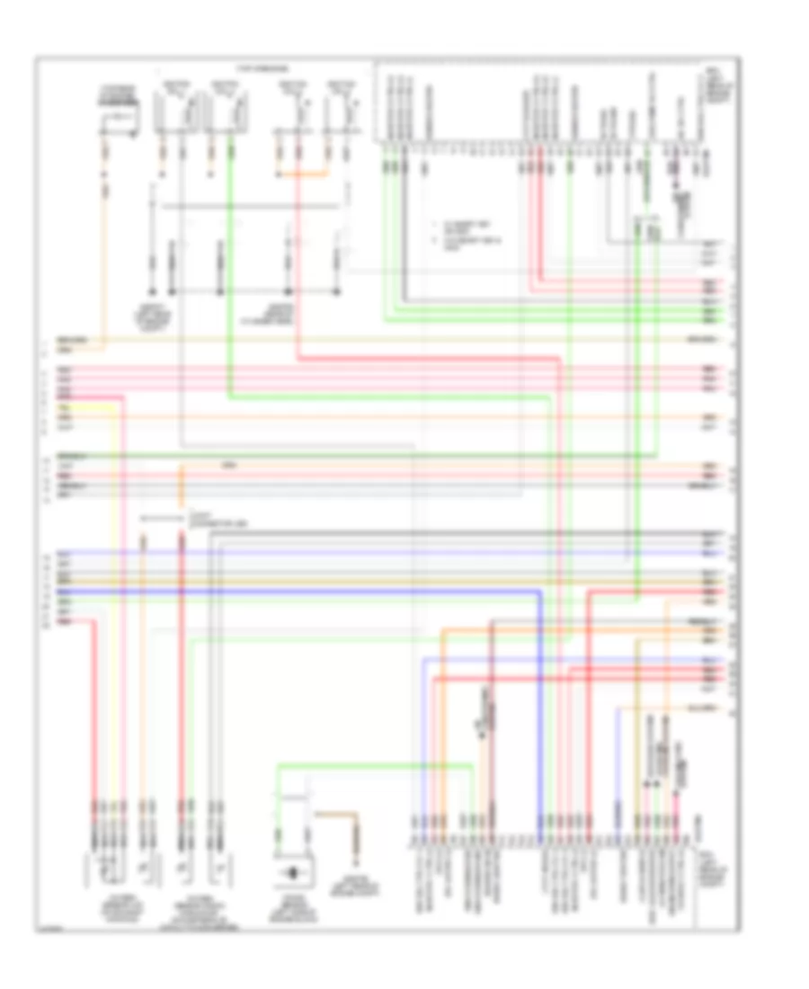
1.6L, Engine Performance Wiring Diagram, with DCT (3 of 5) for Hyundai Veloster 2014
List of elements for 1.6L, Engine Performance Wiring Diagram, with DCT (3 of 5) for Hyundai Veloster 2014:
- (rear of engine) gggd09
- (top of engine)
- A/con rly ctrl
- Air
- Alternator com
- Blower sw in
- Brake light sw
- Brake test sw
- C/fan rly ctrl hi
- C/fan rly ctrl lo
- Condenser (top rear of engine)
- Conditioning system
- Cooling fans system
- Cvvt exhaust
- Cvvt intake
- Defogger system
- Ecm (left rear of engine compt)
- Ects gnd
- Ects sig
- Eggd-ma
- Elec load defroster
- Engine rpm output
- Etc output (+)
- Etc output (-)
- Fpcv (+)
- Fpcv (-)
- Ftps sig
- Fuel pump rly ctrl (or ccvt ctrl)
- Gggd06 (left rear of engine compt)
- Gggd07 (left rear of engine compt)
- Ign coil ctrl cyl 1
- Ign coil ctrl cyl 2
- Ign coil ctrl cyl 3
- Ign coil ctrl cyl 4
- Ignition coil 1
- Ignition coil 2
- Ignition coil 3
- Ignition coil 4
- Injector 1 ctrl (+)
- Injector 1 ctrl (-)
- Injector 2 ctrl (+)
- Injector 2 ctrl (-)
- Injector 3 ctrl (+)
- Injector 3 ctrl (-)
- Injector 4 ctrl (+)
- Injector 4 ctrl (-)
- Knock sensor (left side of engine block)
- Knock sensor gnd
- Knock sensor sig
- Nca
- Oxygen sensor (down) (in exhaust, downstream of catalytic converter)
- Oxygen sensor (up) (on exhaust manifold)
- Pnk
- Red
- Sensor heater
- System conditioning air
- System cooling fans
- Vis ctrl
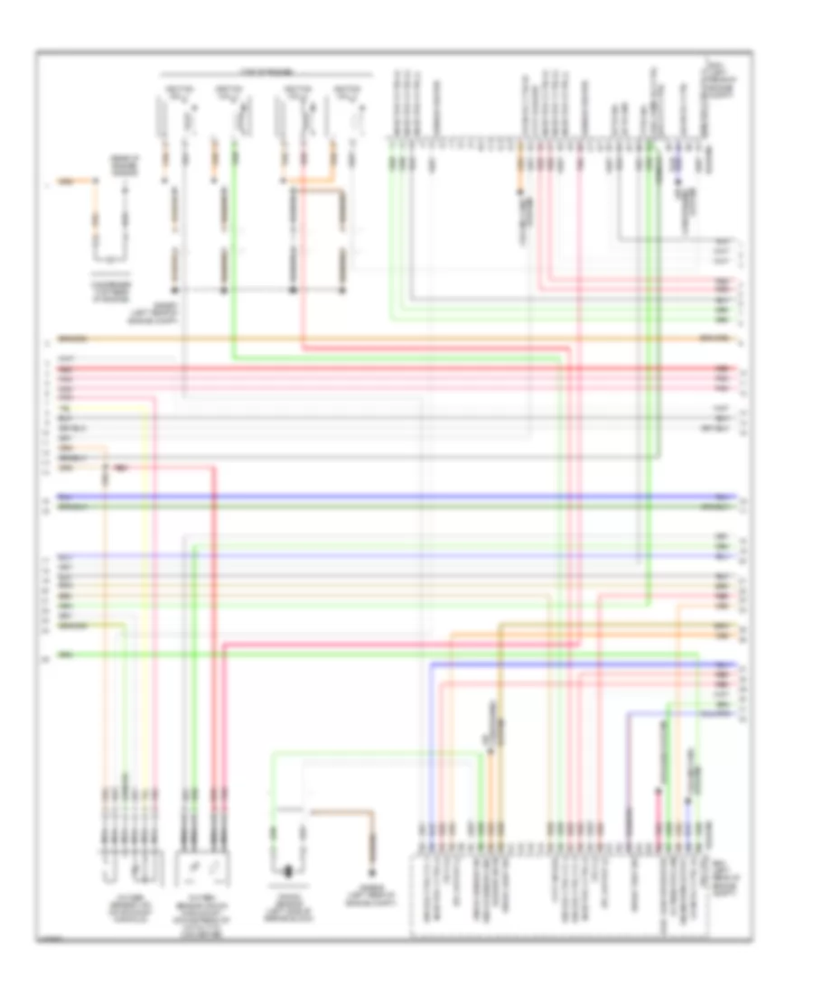
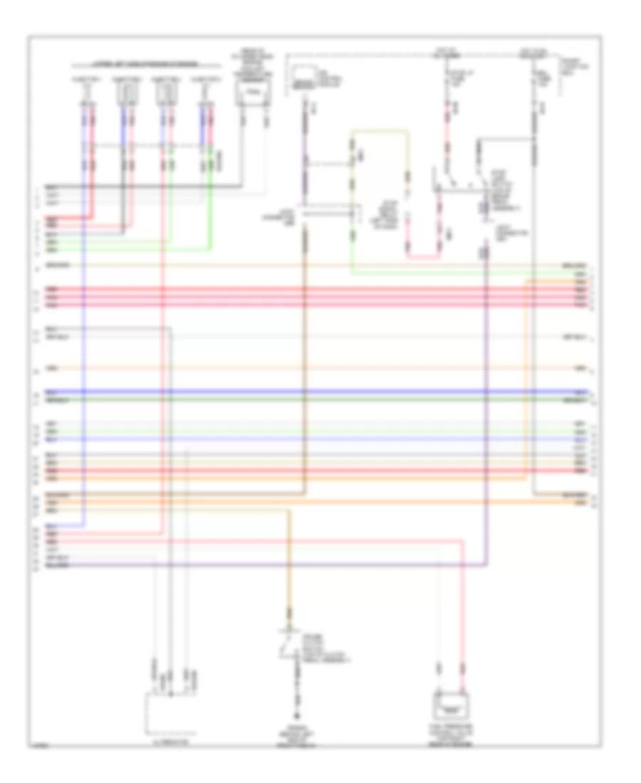
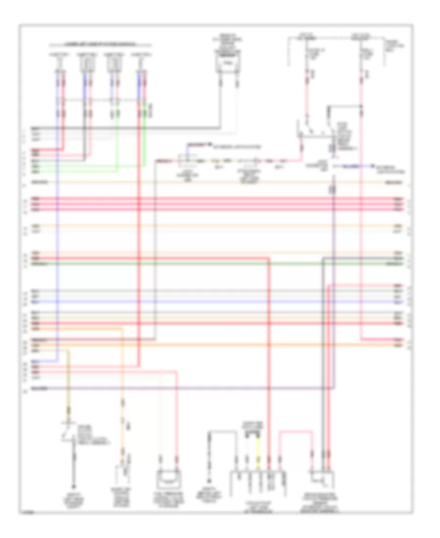
1.6L, Engine Performance Wiring Diagram, with DCT (4 of 5) for Hyundai Veloster 2014
List of elements for 1.6L, Engine Performance Wiring Diagram, with DCT (4 of 5) for Hyundai Veloster 2014:
- (rear of cylinder head) engine coolant temperature sensor
- (under left side of intake manifold)
- Alternator
- Brake switch
- Ecu 1 fuse 10a
- Eggginj
- Em11
- Exterior lights system
- Fuel pressure control valve (top right rear of engine)
- Hot at all times
- Hot in on or start
- I/p-a
- I/p-m
- I/p-n
- Injector 1
- Injector 2
- Injector 3
- Injector 4
- Ips control module
- Pnk
- Red
- Smart junction box
- Stop lamp switch (top of brake pedal assembly)
- Stop lp fuse 15a
- Stop signal relay (left side of dash)
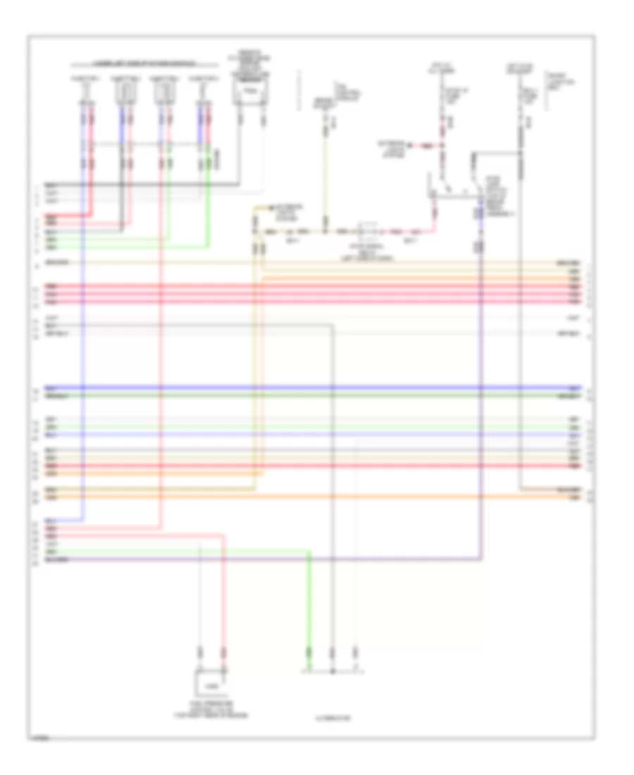
1.6L, Engine Performance Wiring Diagram, with DCT (5 of 5) for Hyundai Veloster 2014
List of elements for 1.6L, Engine Performance Wiring Diagram, with DCT (5 of 5) for Hyundai Veloster 2014:
- (center of dash) smart key control module
- (left rear of engine compt) gggd06
- A/c pressure in
- A/c sw in
- Accel pedal position sensor (top of accelerator pedal assembly)
- Air conditioning system
- Alternator pwm
- Aps 1 gnd
- Aps 1 sig
- Aps 2 gnd
- Aps 2 sig
- Apt sig
- C-can transceiver
- Check engine ind
- Cluster fuse 10a
- Computer data lines system
- Ecm (left rear of engine compt)
- Eggd-mk
- Em11
- Ems com
- Eng ctrl rly ctrl
- Engine rpm
- Etc motor & throttle position sensor (on throttle body)
- Ftps gnd
- Fuel tank sensor
- Gnd
- Hot at all times
- Hot in on or start
- I/p-g
- I/p-h
- Immo ind
- Immobilizer module (top left of dash)
- Instrument cluster
- Leak current autocut device
- M13-a
- M13-b
- M13-c
- Mcu
- Memory fuse 10a
- Memory power
- Mf11
- Motor
- On/start i/p
- Pnk
- Red
- Sensor gnd
- Sensor sig
- Smart junction box
- Stop lamp signal
- Throttle position sensor
- Tps gnd
- Tps1 sig
- Tps2 sig
- W/ smart key
- W/o smart key
- Wiper sw in
- Wiper/washer system
1.6L, Engine Performance Wiring Diagram, without DCT (1 of 5) for Hyundai Veloster 2014
List of elements for 1.6L, Engine Performance Wiring Diagram, without DCT (1 of 5) for Hyundai Veloster 2014:
- A/c pressure transducer (lower right rear of engine compt)
- Alt fuse 125a
- Apt gnd
- Battery
- Battery box
- Body ground
- C-can hi
- C-can lo
- Ckps gnd
- Ckps sig
- Cmps gnd
- Cmps sig
- Computer data lines system
- E/r fuse & relay box (on left side of engine compt)
- Ecm (left rear of engine compt)
- Ecu 1 fuse 30a
- Ecu 2 fuse 15a
- Ecu 4 fuse 15a
- Ee01
- Ef11
- Eggg-mk
- Eggginj
- Eng ctrl rly ctrl
- Engine control relay
- Fuel pump relay
- Fuel pump rly ctrl (or ccv ctrl)
- Fuel tank pressure sensor (part of fuel sender & fuel pump motor assembly)
- Iat sig
- Immo data line
- Lin communication
- Lin line
- Map sensor (on throttle body)
- Multi fuse
- Nernst voltage
- Pcsv ctrl
- Pnk
- Pumping current
- Rail pressure sensor (front of fuel rail assembly)
- Red
- Rps gnd
- Rps sig
- Sensor fuse 10a
- Sensor fuse 15a
- Sensor fuse 20a
- Sensor gnd
- Sensor sig
- Snsr +
- Start rly ctrl
- Start sig i/p
- Starting/ charging system
- Trim resistor
- Vehicle speed in
- Virtual gnd
- W/ smart key or immo
- W/o smart key & immo
1.6L, Engine Performance Wiring Diagram, without DCT (2 of 5) for Hyundai Veloster 2014
List of elements for 1.6L, Engine Performance Wiring Diagram, without DCT (2 of 5) for Hyundai Veloster 2014:
- (at left "b" pillar)
- (center of dash) smart key control module
- (top center of fuel tank) fuel sender & fuel pump motor
- Camshaft position sensor (exhaust) (right rear of cylinder head)
- Camshaft position sensor (intake) (left rear of cylinder head)
- Canister close valve (above left rear suspension)
- Crankshaft position sensor (left rear of engine block)
- Ef11
- Em11
- Em61
- Esc module
- Fuel
- Fuel pump motor
- Gf06
- Instrument cluster system
- Joint connector uec
- M13-b
- Mf11
- Oil control valve 1 (intake) (left front of cylinder head)
- Oil control valve 2 (exhaust) (top front of cylinder head)
- Pnk
- Purge control solenoid valve (left rear of engine)
- Red
- Sender
- Variable intake solenoid valve (left rear of engine)
- W/ smart key or immo
- W/o smart key & immo
1.6L, Engine Performance Wiring Diagram, without DCT (3 of 5) for Hyundai Veloster 2014
List of elements for 1.6L, Engine Performance Wiring Diagram, without DCT (3 of 5) for Hyundai Veloster 2014:
- (or ccv ctrl) fuel pump rly ctrl
- (top of engine)
- A/con rly ctrl
- Air
- Alternator com
- Blower sw in
- Brake light sw
- Brake test sw
- C/fan rly ctrl hi
- C/fan rly ctrl lo
- Clutch switch
- Condenser (top rear of engine)
- Conditioning system
- Cooling fans system
- Cvvt exhaust
- Cvvt intake
- Defogger system
- Ecm (left rear of engine compt)
- Ects gnd
- Ects sig
- Eggg-ma
- Elec load defroster
- Engine rpm output
- Etc output (+)
- Etc output (-)
- Fpcv (+)
- Fpcv (-)
- Ftps sig
- Gggg06 (left rear of engine compt)
- Gggg07 (left rear of engine compt)
- Gggg09 (rear of engine)
- Ign coil ctrl cyl 1
- Ign coil ctrl cyl 2
- Ign coil ctrl cyl 3
- Ign coil ctrl cyl 4
- Ignition coil 1
- Ignition coil 2
- Ignition coil 3
- Ignition coil 4
- Injector 1 ctrl (+)
- Injector 1 ctrl (-)
- Injector 2 ctrl (+)
- Injector 2 ctrl (-)
- Injector 3 ctrl (+)
- Injector 3 ctrl (-)
- Injector 4 ctrl (+)
- Injector 4 ctrl (-)
- Joint connector ued
- Knock sensor (left side of engine block)
- Knock sensor gnd
- Knock sensor sig
- Nca
- Oxygen sensor (down) (in exhaust, downstream of catalytic converter)
- Oxygen sensor (up) (on exhaust manifold)
- Pnk
- Red
- Sensor heater
- System conditioning air
- System cooling fans
- Vis ctrl
1.6L, Engine Performance Wiring Diagram, without DCT (4 of 5) for Hyundai Veloster 2014
List of elements for 1.6L, Engine Performance Wiring Diagram, without DCT (4 of 5) for Hyundai Veloster 2014:
- (rear of cylinder head) engine coolant temperature sensor
- (upper left side of engine of engine)
- Alternator
- Brake switch
- Cruise clutch switch (top of clutch pedal assembly)
- Ecu fuse 10a
- Egg06
- Eggg06
- Eggginj
- Em11
- Fuel pressure control valve (top right rear of engine)
- Gggg02 (behind left end of front fascia)
- Hot at all times
- Hot in on or start
- I/p-a
- I/p-m
- I/p-n
- Injector 1
- Injector 2
- Injector 3
- Injector 4
- Ips control module
- Joint connector uea
- Joint connector ueb
- Pnk
- Red
- Smart junction box
- Stop lamp switch (top of brake pedal assembly)
- Stop lp fuse 15a
- Stop signal relay (left side of dash)
1.6L, Engine Performance Wiring Diagram, without DCT (5 of 5) for Hyundai Veloster 2014
List of elements for 1.6L, Engine Performance Wiring Diagram, without DCT (5 of 5) for Hyundai Veloster 2014:
- (center of dash) smart key control module
- (left rear of engine compt) gggg06
- A/c pressure in
- A/c sw in
- Accel pedal position sensor (top of accelerator pedal assembly)
- Air conditioning system
- Alternator pwm
- Aps 1 gnd
- Aps 1 sig
- Aps 2 gnd
- Aps 2 sig
- Apt sig
- Battery power
- C-can transceiver
- Check engine ind
- Cluster fuse 10a
- Computer data lines system
- Ecm (left rear of engine compt)
- Eggg-mk
- Em11
- Ems com
- Eng ctrl rly 'on' i/p
- Engine rpm
- Etc motor & throttle position sensor (on throttle body)
- Ftps gnd
- Fuel tank sensor
- Gnd
- Hot at all times
- Hot in on or start
- I/p-g
- I/p-h
- Immo ind
- Immobilizer module (top left of dash)
- Instrument cluster
- Leak current autocut device
- M13-a
- M13-b
- M13-c
- Mcu
- Memory fuse 10a
- Mf11
- Motor
- On/start i/p
- Pnk
- Red
- Sensor gnd
- Sensor sig
- Smart junction box
- Stop lamp signal
- Throttle position sensor
- Tps 1 sig
- Tps 2 sig
- Tps gnd
- W/ smart key
- W/o smart key
- Wiper sw in
- Wiper/washer system
1.6L TURBO
1.6L Turbo, Engine Performance Wiring Diagram, A/T (1 of 7) for Hyundai Veloster 2014
List of elements for 1.6L Turbo, Engine Performance Wiring Diagram, A/T (1 of 7) for Hyundai Veloster 2014:
- A/c rly ctrl
- Air conditioning system
- Alt fuse 150a
- Battery
- Battery box
- Body ground
- C-can high
- C-can low
- C-can2 high
- C-can2 low
- Camshaft position sensor (exhaust) (right rear of cylinder head)
- Camshaft position sensor (intake) (left rear of cylinder head)
- Ckps gnd
- Ckps signal
- Cmps exhaust signal
- Cmps intake gnd
- Cmps intake signal
- Computer data lines system
- Crankshaft position sensor (left rear of engine block)
- E/r fuse & relay box (on left side of engine compt)
- Ecu 1 fuse 30a
- Ecu 2 fuse 15a
- Ecu 4 fuse 15a
- Ee31
- Eggt-ak
- Eng ctrl rly ctrl
- Eng ctrl rly on input
- Eng rpm output
- Engine control relay
- Fuel pump relay
- Fuel pump rly ctrl (or ccv ctrl)
- Gggt01 (behind left end of front fascia)
- Ignition coil cyl 1 ctrl
- Ignition coil cyl 3 ctrl
- Ignition coil cyl 4 ctrl
- Immo data line
- Intake cvvt
- Lin communication
- Lin line
- Multi fuse
- On/start pwr
- Pcm (powertrain control module) (left rear of engine compt)
- Pnk
- Rcv ctrl
- Red
- Sensor 1 fuse 20a
- Sensor 2 fuse 10a
- Sensor 3 fuse 15a
- Snsr +
- Start rly ctrl
- Start sig input
- Starting/charging system
- Stop lamp sw
- Vacuum pump fuse 15a
- Vacuum pump relay
- Vehicle speed input
- W/ smart key or immo
- W/o smart key & immo
- Wgv ctrl
- Wiper sw input
- Wiper/ washer system
1.6L Turbo, Engine Performance Wiring Diagram, A/T (2 of 7) for Hyundai Veloster 2014
List of elements for 1.6L Turbo, Engine Performance Wiring Diagram, A/T (2 of 7) for Hyundai Veloster 2014:
- (center of dash) smart key control module
- (top center of fuel tank) fuel sender & fuel pump motor
- (top front of cylinder head)
- B-up lamp 1 fuse 15a
- Canister close valve (above left rear suspension)
- Ef11
- Eggtcr
- Em11
- Em61
- Esc module
- Fuel pump motor
- Fuel sender
- Gf06 (at left "b" pillar)
- Hot in on or start
- I/p-m
- Instrument cluster system
- Joint connector uec
- M13-b
- Mf11
- Oil control valve 1 (intake) (left front of cylinder head)
- Oil control valve 2 (exhaust)
- Pnk
- Purge control solenoid valve (left rear of engine)
- Recirculation valve (left front of engine compt)
- Red
- Smart junction box
- Vacuum pump fuse 15a
- W/ smart key or immo
- W/o smart key & immo
- Waste gate solenoid valve (top front of engine)
1.6L Turbo, Engine Performance Wiring Diagram, A/T (3 of 7) for Hyundai Veloster 2014
List of elements for 1.6L Turbo, Engine Performance Wiring Diagram, A/T (3 of 7) for Hyundai Veloster 2014:
- (left side of engine block) knock sensor
- (or ccv ctrl) fuel pump rly ctrl
- (top of engine)
- (top rear of engine) condenser
- (top right rear of engine) fuel pressure control valve
- Alternator com
- Apt gnd
- Apt signal
- Apt/rps/bps sply
- Cmps exhaust gnd
- Cooling fans pwm ctrl
- Cooling fans system
- Defogger system
- Eggt-ak
- Elec load defroster
- Eng ctrl rly on i/p
- Etc output (+)
- Etc output (-)
- Exhaust cvvt
- Ftps gnd
- Gggt06 (left rear of engine compt)
- Gggt07 (left rear of engine compt)
- Gggt09 (rear of cylinder head)
- Gnd
- Iat signal
- Ignition coil 1
- Ignition coil 2
- Ignition coil 3
- Ignition coil 4
- Ignition coil cyl 2 ctrl
- Mem pwr
- Pcm (powertrain control module) (left rear of engine compt)
- Pnk
- Red
- Rps gnd
- Rps signal
- Sensor gnd
- Sensor signal
- Vacuum sensor gnd
1.6L Turbo, Engine Performance Wiring Diagram, A/T (4 of 7) for Hyundai Veloster 2014
List of elements for 1.6L Turbo, Engine Performance Wiring Diagram, A/T (4 of 7) for Hyundai Veloster 2014:
- (left side of transaxle) vacuum pump
- A/c pressure transducer (lower right rear of engine compt)
- Alternator
- Battery
- Brake booster vacuum pressure sensor (on brake vacuum booster assembly)
- C-can high
- C-can low
- Clockspring
- Com
- Computer data lines system
- Down shift
- Ef11
- Eggtinj
- Em11
- Fuel tank pressure sensor (part of fuel sender & fuel pump motor assembly)
- Gggt01 (behind left end of front fascia)
- Gm02 (top left side of dash)
- Gnd
- Joint connector umb
- Left paddle shift switch
- M01-h
- M01-r
- Map sensor (on throttle body)
- Multi-function switch
- Nca
- Pnk
- Rail pressure sensor (front of fuel rail assembly)
- Red
- Right paddle shift switch
- Select switch
- Shift down
- Shift up
- Signal sw vacc pmp rly ctrl
- Sport mode switch
- Steering wheel
- Up shift
- W/ heated steering wheel
- W/o heated steering wheel
1.6L Turbo, Engine Performance Wiring Diagram, A/T (5 of 7) for Hyundai Veloster 2014
List of elements for 1.6L Turbo, Engine Performance Wiring Diagram, A/T (5 of 7) for Hyundai Veloster 2014:
- Accel pedal position sensor (top of accelerator pedal assembly)
- Alternator pwm
- Aps 1 gnd
- Aps 1 signal
- Aps 2 gnd
- Aps 2 signal
- Ats signal
- Blower sw input
- Brake sw
- Conditioning system air
- Down shift
- Ects signal
- Eggt-aa
- Exterior lights system
- Fpcv (+)
- Fpcv (-)
- Ftps signal
- Fuel tank level
- Injector 1 ctrl (-)
- Injector 2 ctrl (-)
- Injector 3 ctrl (-)
- Injector 4 ctrl (-)
- Input spd signal
- Joint connector ued
- Knock sens gnd
- Knock sens signal
- Nca
- Nernst voltage
- Oil temp sensor (-)
- On/st in
- Output spd signal
- Oxygen sensor (down) (in exhaust, downstream of catalytic converter)
- Oxygen sensor (up) (on exhaust manifold)
- P/n switch
- Pcm (powertrain control module) (left rear of engine compt)
- Pnk
- Posi sw code s1
- Posi sw code s2
- Posi sw code s3
- Posi sw code s4
- Pumping current
- Red
- Sensor signal
- Sig 1
- Sig 2
- Sig 3
- Sig 4
- Solenoid pwr 1
- Solenoid pwr 2
- Ss_a
- Starting/ charging system
- Transaxle range switch (top of transaxle)
- Trim resistor
- Vertual gnd
1.6L Turbo, Engine Performance Wiring Diagram, A/T (6 of 7) for Hyundai Veloster 2014
List of elements for 1.6L Turbo, Engine Performance Wiring Diagram, A/T (6 of 7) for Hyundai Veloster 2014:
- (under left side of intake manifold)
- 26 vfs
- 35r vfs
- Atm solenoid (top of transaxle)
- Brake switch
- Ecu fuse 10a
- Eggtinj
- Em11
- Hot at all times
- Hot in on or start
- I/p-a
- I/p-m
- I/p-n
- Injector 1
- Injector 2
- Injector 3
- Injector 4
- Input speed
- Ips control module
- Joint connector uea
- Joint connector ueb
- Line vfs
- Od vfs
- Output speed
- Pnk
- Red
- Sensor oil temp
- Smart junction box
- Ss-a
- Ss-b
- Stop lamp switch (top of brake pedal assembly)
- Stop lp fuse 15a
- Stop signal relay (left side of dash)
- T/con vfs
- Ud vfs
1.6L Turbo, Engine Performance Wiring Diagram, A/T (7 of 7) for Hyundai Veloster 2014
List of elements for 1.6L Turbo, Engine Performance Wiring Diagram, A/T (7 of 7) for Hyundai Veloster 2014:
- (center of dash)
- 26_vfs
- 35r_vfs
- A/c pressure in
- A/c sw in
- Air conditioning system
- Ambient temperature sensor (behind center of front fascia)
- Ats gnd
- Boost pressure sensor (left front of engine compt)
- Bps gnd
- Bps signal
- C-can transceiver
- Check engine ind
- Cluster fuse 10a
- Computer data lines system
- Cylinder head)
- Ects gnd
- Eggt-aa
- Em11
- Ems com
- Engine coolant temperature sensor (rear of
- Engine rpm
- Etc motor & throttle position sensor (on throttle body)
- Gm01 (top left side of dash)
- Hot at all times
- Hot in on or start
- I/p-g
- I/p-h
- Immo ind
- Immobilizer module (top left of dash)
- Injector 1 ctrl (+)
- Injector 2 ctrl (+)
- Injector 3 ctrl (+)
- Injector 4 ctrl (+)
- Instrument cluster
- Leak current autocut device
- Line vfs
- M13-a
- M13-b
- M13-c
- Mcu
- Memory fuse 10a
- Mf11
- Motor
- Od_vfs
- Oil temp sensor (+)
- Pcm (powertrain control module) (left rear of engine compt)
- Pcsv ctrl
- Pnk
- Red
- Select sw
- Sens gnd
- Sensor heater
- Sgnd
- Smart junction box
- Smart key control module
- Ss_b
- Stop lamp signal
- T/con_vfs
- Throttle position sensor
- Tps 1 signal
- Tps 2 signal
- Tps gnd
- Trip (-)
- Ud_vfs
- Up shift
- W/ smart key
- W/o smart key
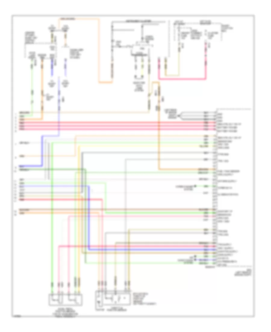
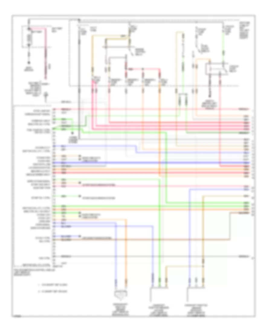
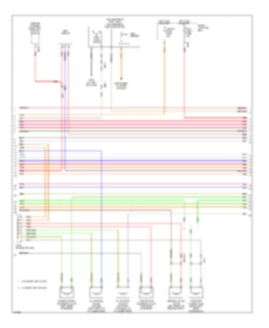
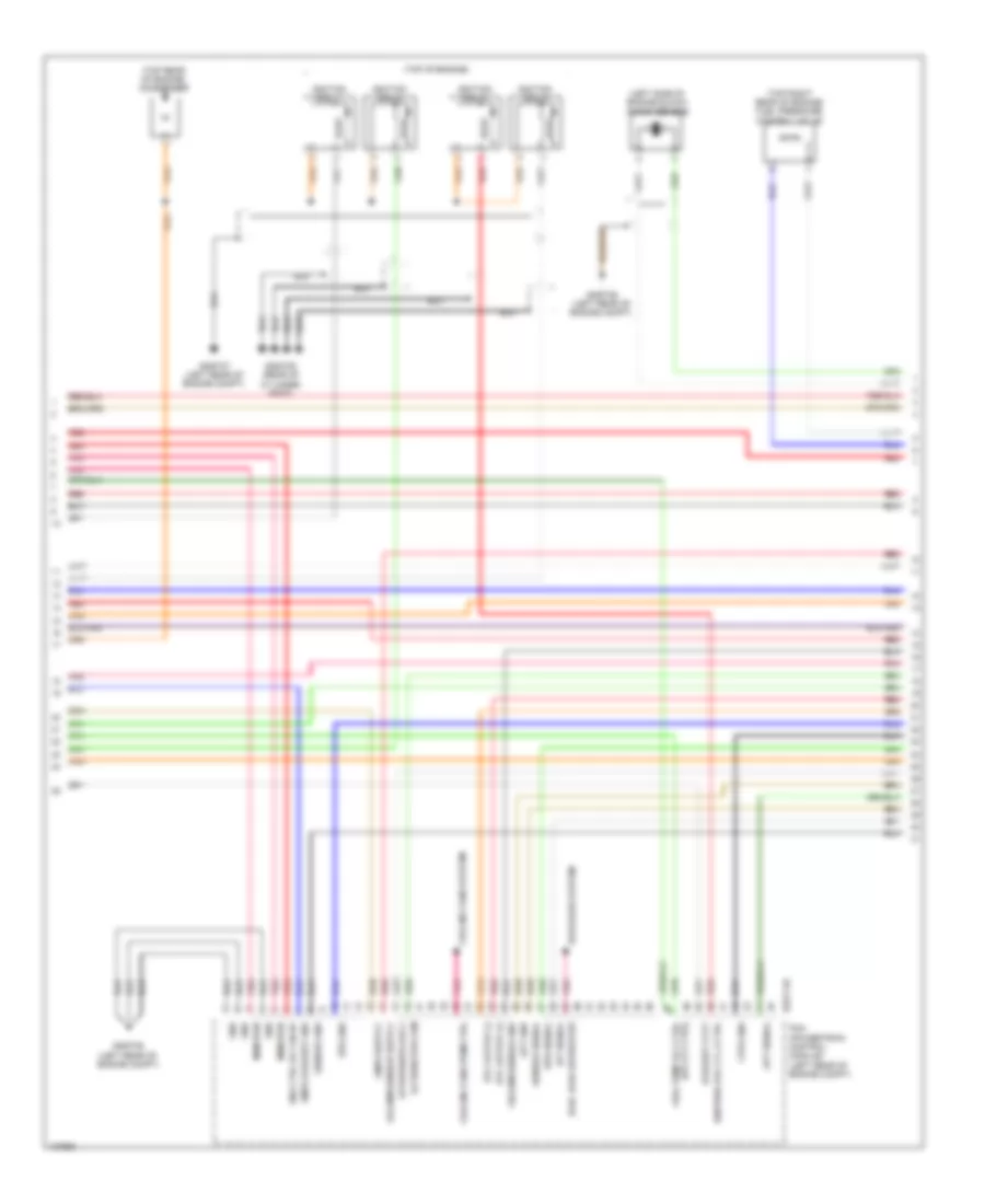
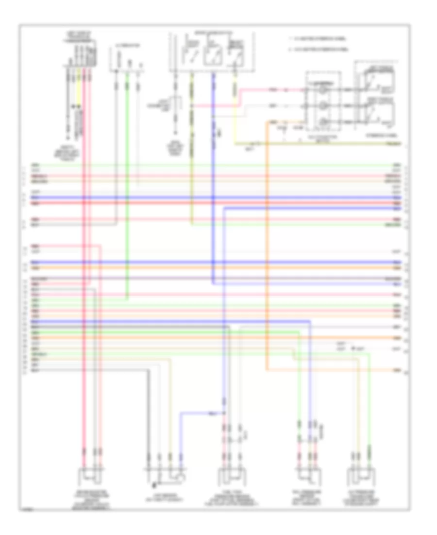
1.6L Turbo, Engine Performance Wiring Diagram, M/T (1 of 5) for Hyundai Veloster 2014
List of elements for 1.6L Turbo, Engine Performance Wiring Diagram, M/T (1 of 5) for Hyundai Veloster 2014:
- (not used)
- A/c pressure transducer (lower right rear of engine compt)
- Anti-theft system
- Apt gnd
- Boost pressure sensor (left front of engine compt)
- Bps gnd
- Bps sig
- C-can hi
- C-can lo
- Ccp can hi
- Ccp can lo
- Ckps gnd
- Ckps sig
- Cmps gnd
- Cmps sig
- Computer data lines system
- E/r fuse & relay box (on left side of engine compt)
- Ecm (left rear of engine compt)
- Ecu 1 fuse 30a
- Ecu 2 fuse 15a
- Ecu 4 fuse 15a
- Ef11
- Eggt-mk
- Eggtinj
- Em61
- Eng ctrl rly ctrl
- Engine control relay
- Fuel pump relay
- Fuel pump rly ctrl
- Fuel tank pressure sensor (part of fuel sender & fuel pump motor assembly)
- Gggt01 (behind left end of front fascia)
- Hot at all times
- Iat sig
- Immo data line
- Lin communication
- Map sensor (on throttle body)
- Nernst voltage
- Pcsv ctrl
- Pnk
- Pumping current
- Rail pressure sensor (front of fuel rail assembly)
- Rcv ctrl
- Red
- Rps gnd
- Rps sig
- Sensor fuse 10a
- Sensor fuse 15a
- Sensor fuse 20a
- Sensor gnd
- Sensor sig
- Start rly ctrl
- Start sig in
- Starting/ charging system
- Trim resistor
- Vaccum pump fuse 20a
- Vacuum pump relay
- Vehicle speed in
- Virtual gnd
- W/ smart key or immo
- W/o smart key & immo
- Wgv ctrl
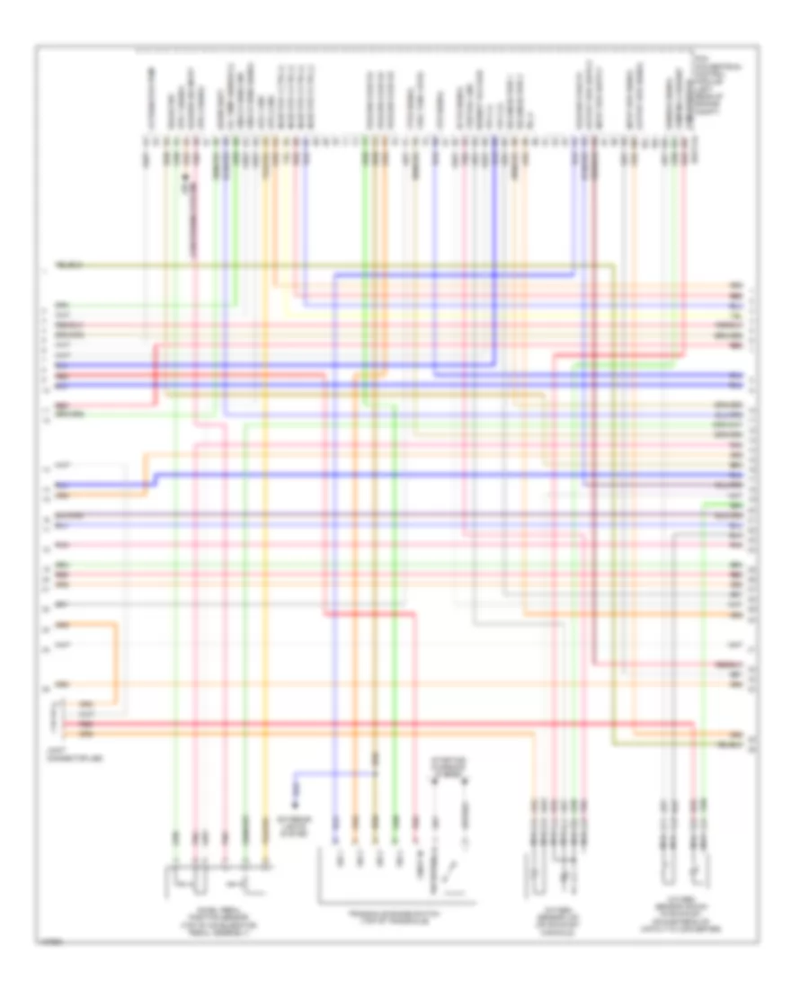
1.6L Turbo, Engine Performance Wiring Diagram, M/T (2 of 5) for Hyundai Veloster 2014
List of elements for 1.6L Turbo, Engine Performance Wiring Diagram, M/T (2 of 5) for Hyundai Veloster 2014:
- (at left "b" pillar)
- (center of dash) smart key control module
- (top center of fuel tank) fuel sender & fuel pump motor
- Camshaft position sensor (exhaust) (right rear of cylinder head)
- Camshaft position sensor (intake) (left rear of cylinder head)
- Canister close valve (above left rear suspension)
- Crankshaft position sensor (left rear of engine block)
- Ef11
- Eggtcr
- Em11
- Em61
- Esc module
- Fuel pump motor
- Fuel sender
- Gf06
- Hot in on or start
- I/p-m
- Joint connector uec
- M13-b
- Mf11
- Oil control valve 1 (intake) (left front of cylinder head)
- Oil control valve 2 (exhaust) (top front of cylinder head)
- Pnk
- Purge control solenoid valve (left rear of engine)
- Recirculation valve (left front of engine compt)
- Red
- Smart junction box
- Vacuum pump fuse 15a
- W/ smart key or immo
- W/o smart key & immo
- Waste gate solenoid valve (top front of engine)
1.6L Turbo, Engine Performance Wiring Diagram, M/T (3 of 5) for Hyundai Veloster 2014
List of elements for 1.6L Turbo, Engine Performance Wiring Diagram, M/T (3 of 5) for Hyundai Veloster 2014:
- (top of engine)
- (top rear of engine) condenser
- A/c rly ctrl
- Air
- Alternator com
- Blower sw in
- Brake light sw
- Brake test sw
- C/fan rly ctrl lo
- Clutch switch
- Conditioning system
- Cooling fans system
- Cvvt exhaust
- Cvvt intake
- Defogger system
- Ecm (left rear of engine compt)
- Ects gnd
- Ects sig
- Eggt-ma
- Elec load defroster
- Engine rpm output
- Etc output (+)
- Etc output (-)
- Fpcv (+)
- Fpcv (-)
- Ftps sig
- Fuel pump rly ctrl
- Gggt06 (left rear of engine compt)
- Gggt07 (left rear of engine compt)
- Gggt09 (rear of cylinder head)
- Ign coil ctrl cyl 1
- Ign coil ctrl cyl 2
- Ign coil ctrl cyl 3
- Ign coil ctrl cyl 4
- Ignition coil 1
- Ignition coil 2
- Ignition coil 3
- Ignition coil 4
- Injector 1 ctrl (+)
- Injector 1 ctrl (-)
- Injector 2 ctrl (+)
- Injector 2 ctrl (-)
- Injector 3 ctrl (+)
- Injector 3 ctrl (-)
- Injector 4 ctrl (+)
- Injector 4 ctrl (-)
- Joint connector ued
- Knock sensor (left side of engine block)
- Knock sensor gnd
- Knock sensor sig
- Nca
- Oxygen sensor (down) (in exhaust, downstream of catalytic converter)
- Oxygen sensor (up) (on exhaust manifold)
- Pnk
- Red
- Sensor heater
- Starting/ charging system
- System conditioning air
- W/ smart key or immo
- W/o smart key & immo
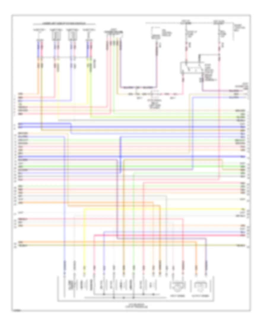
1.6L Turbo, Engine Performance Wiring Diagram, M/T (4 of 5) for Hyundai Veloster 2014
List of elements for 1.6L Turbo, Engine Performance Wiring Diagram, M/T (4 of 5) for Hyundai Veloster 2014:
- (rear of cylinder head) engine coolant temperature sensor
- (under left side of intake manifold)
- Brake booster vacuum pressure sensor (on brake vacuum booster assembly)
- C-can high
- C-can low
- Computer data lines system
- Cruise clutch switch (top of clutch pedal assembly)
- Ecu 1 fuse 10a
- Eggtinj
- Em11
- Exterior lights system
- Fuel pressure control valve (top right rear of engine)
- Gggt01 (behind left end of front fascia)
- Gggt07 (left rear of engine compt)
- Gnd
- Hot at all times
- Hot in on or start
- I/p-m
- I/p-n
- Injector 1
- Injector 2
- Injector 3
- Injector 4
- Joint connector uea
- Joint connector ueb
- M13-a
- Pnk
- Red
- Rpm
- Sig sw
- Smart junction box
- Smart key control module (center of dash)
- Stop lamp switch (top of brake pedal assembly)
- Stop lp fuse 15a
- Stop signal relay (left side of dash)
- Vacc pmp rly ctrl
- Vacuum pump (left side of transaxle)
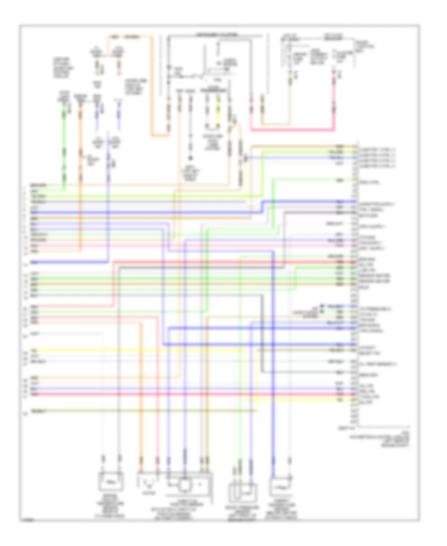
1.6L Turbo, Engine Performance Wiring Diagram, M/T (5 of 5) for Hyundai Veloster 2014
List of elements for 1.6L Turbo, Engine Performance Wiring Diagram, M/T (5 of 5) for Hyundai Veloster 2014:
- A/c pressure in
- A/c sw in
- Accel pedal position sensor (top of accelerator pedal assembly)
- Air conditioning system
- Alternator pwm
- Ambient temperature sensor (behind center of front fascia)
- Aps 1 gnd
- Aps 1 sig
- Aps 2 gnd
- Aps 2 sig
- Apt sig
- Ats gnd
- Ats sig
- Bvs gnd
- C-can transceiver
- Check engine ind
- Cluster fuse 10a
- Computer data lines system
- Ecm (left rear of engine compt)
- Eggt-mk
- Em11
- Eng ctrl rly ctrl
- Etc motor & throttle position sensor (on throttle body)
- Ftps gnd
- Fuel tank sensor
- Gggt06 (left rear of engine compt)
- Gnd
- Hot in on or start
- I/p-g
- Instrument cluster
- Mcu
- Memory power
- Mf11
- Motor
- On/start in
- Pnk
- Red
- Sensor gnd
- Sensor sig
- Smart junction box
- Starting/charging system
- Throttle position sensor
- Tps 1 sig
- Tps 2 sig
- Tps gnd
- Wiper sw in
- Wiper/washer system