SUPPLEMENTAL RESTRAINTS
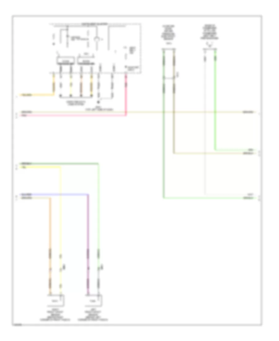
Supplemental Restraints Wiring Diagram, Advanced (1 of 3) for Hyundai Veloster 2014

List of elements for Supplemental Restraints Wiring Diagram, Advanced (1 of 3) for Hyundai Veloster 2014:
- A/bag fuse 15a
- A/bag ind fuse 10a
- C-can high
- C-can low
- Clock spring
- Cluster fuse 10a
- Computer data lines system
- Crash input
- Crash output
- Dab high
- Dab low
- Dr fis hi
- Dr fis low
- Driver air bag
- Driver seat belt switch
- Driver seat warmer switch
- Gf05 (under center console)
- Ground
- Hot in on or start
- I/p-b
- I/p-c
- I/p-f
- I/p-g
- Ips control module
- Lamp telltale
- M51
- Mf11
- Mts module (below right side of dash)
- Multi- function switch
- Nca
- On/start i/p
- On/start input
- Pab 1st high
- Pab 1st low
- Pab 2nd high
- Pab 2nd low
- Pass fis hi
- Pass fis low
- Passenger air bag 1 (behind right side of dash)
- Passenger air bag 2 (behind right side of dash)
- Passenger occupant detection sensor (under passenger's seat)
- Pnk
- Red
- Side a/bag
- Smart junction box
- Srs control module (under floor console)
- Steering wheel
- Telltale
- Telltale lamp
- W/ seat warmer
- W/o seat warmer
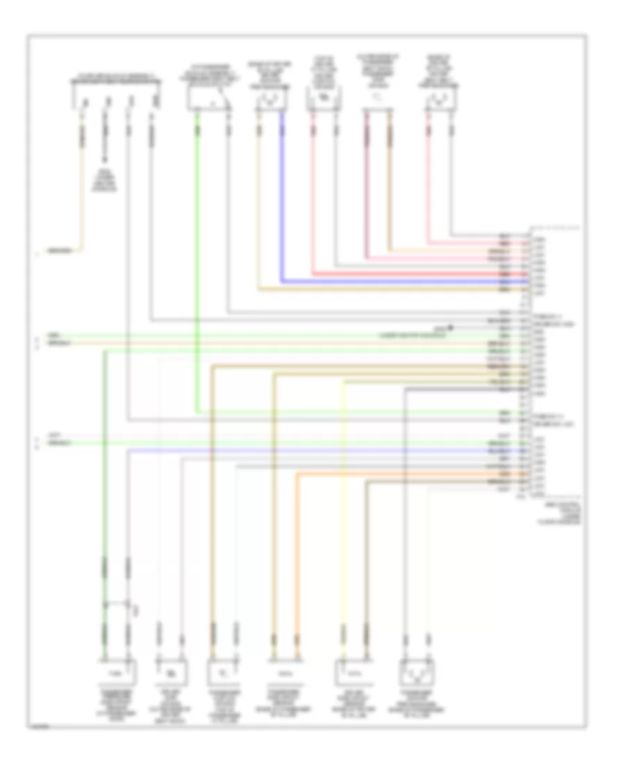
Supplemental Restraints Wiring Diagram, Advanced (2 of 3) for Hyundai Veloster 2014
List of elements for Supplemental Restraints Wiring Diagram, Advanced (2 of 3) for Hyundai Veloster 2014:
- (base of passenger "b" pillar) passenger seat belt pretensioner
- (in driver door) driver
- Air bag ind
- B-can transceiver
- C-can transceiver
- Computer data lines system
- Em11
- Em61
- Fd11
- Gm01 (top left side of dash)
- High
- Instrument cluster
- Left front impact sensor (behind left corner of front fascia)
- Low
- Mcu
- On/start input
- Pnk
- Pressure side impact sensor
- Right front impact sensor (behind right corner of front fascia)
- Seat belt ind
- Sgnd 1
- Sgnd 2
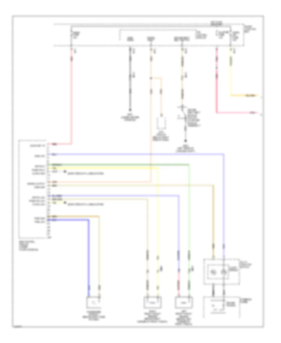
Supplemental Restraints Wiring Diagram, Advanced (3 of 3) for Hyundai Veloster 2014
List of elements for Supplemental Restraints Wiring Diagram, Advanced (3 of 3) for Hyundai Veloster 2014:
- (base of driver "b" pillar) driver anchor pretensioner
- (base of driver "b" pillar) driver seat belt pretensioner
- (in driver buckle assembly) driver seat belt buckle switch
- (in passenger buckle assembly) passenger seat belt buckle switch
- (outer edge of passenger seat back) passenger side air bag
- (top of driver "c" pillar) driver curtain air bag
- Driver side air bag (outer edge of driver seat back)
- Driver side impact sensor (base of driver "b" pillar)
- Driver sw high
- Driver sw low
- F15
- Fd21
- Gf05 (under center console)
- Gnd
- High
- Ind
- Low
- Pass sw (+)
- Pass sw (-)
- Passenger anchor pretensioner (base of passenger "b" pillar)
- Passenger curtain air bag (top of passenger "c" pillar)
- Passenger pressure side impact sensor (in passenger door)
- Passenger side impact sensor (base of passenger "b" pillar)
- Red
- Srs control module (under floor console)
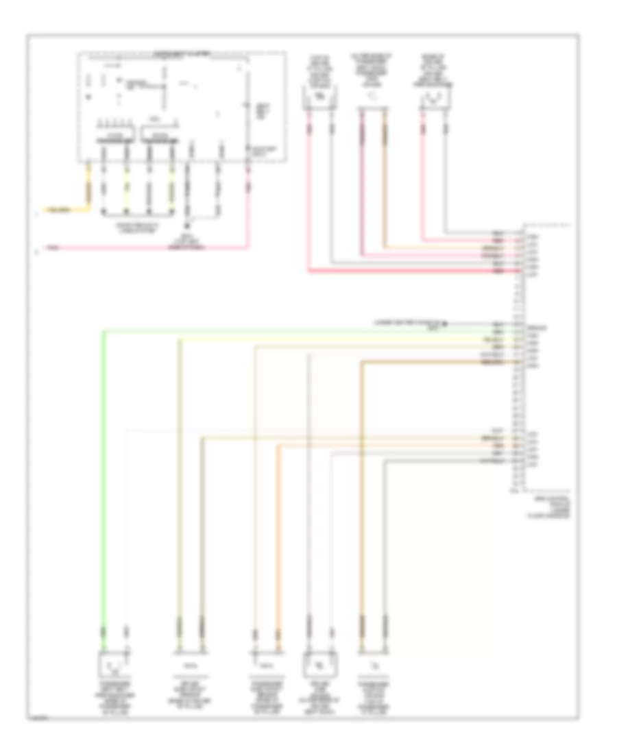
Supplemental Restraints Wiring Diagram, Depowered (1 of 2) for Hyundai Veloster 2014
List of elements for Supplemental Restraints Wiring Diagram, Depowered (1 of 2) for Hyundai Veloster 2014:
- A/bag fuse 15a
- A/bag ind fuse 10a
- C-can high
- C-can low
- Clock spring
- Cluster fuse 10a
- Computer data lines system
- Crash input
- Crash output
- Dab high
- Dab low
- Dr fis hi
- Dr fis low
- Driver air bag
- Driver seat belt buckle switch (in driver buckle assembly)
- Driver seat belt switch
- Em11
- Em61
- Gf03 (left rear of luggage compt)
- Gf07 (under center console)
- Hot in on or start
- I/p-b
- I/p-c
- I/p-f
- I/p-g
- Ips control module
- Left front impact sensor (behind left corner of front fascia)
- M51
- Mf11
- Mts module (below right side of dash)
- Multi- function switch
- Nca
- On/start i/p
- Pab high
- Pab low
- Pass fis hi
- Pass fis low
- Passenger air bag 1 (behind right side of dash)
- Pnk
- Red
- Right front impact sensor (behind right corner of front fascia)
- Side a/bag
- Smart junction box
- Srs control module (under floor console)
- Steering wheel
Supplemental Restraints Wiring Diagram, Depowered (2 of 2) for Hyundai Veloster 2014
List of elements for Supplemental Restraints Wiring Diagram, Depowered (2 of 2) for Hyundai Veloster 2014:
- (base of driver "b" pillar) driver seat belt pretensioner
- (outer edge of passenger seat back) passenger side air bag
- (top of driver "c" pillar) driver curtain air bag
- (under center console)
- Air bag ind
- B-can transceiver
- C-can transceiver
- Computer data lines system
- Driver side air bag (outer edge of driver seat back)
- Driver side impact sensor (base of driver "b" pillar)
- F15
- Gf07
- Gm01 (top left side of dash)
- Ground
- High
- Instrument cluster
- Low
- Mcu
- On/start input
- Passenger curtain air bag (top of passenger "c" pillar)
- Passenger seat belt pretensioner (base of passenger "b" pillar)
- Passenger side impact sensor (base of passenger "b" pillar)
- Pnk
- Red
- Seat belt ind
- Sgnd 1
- Sgnd 2
- Srs control module (under floor console)