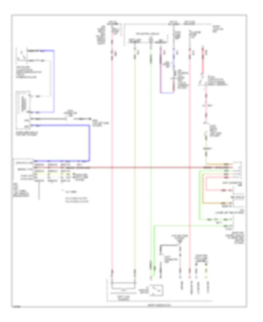
SHIFT INTERLOCK
Shift Interlock Wiring Diagram for Hyundai Veloster 2014
List of elements for Shift Interlock Wiring Diagram for Hyundai Veloster 2014:
- "p" pos sw
- "p" position switch
- (+)
- (-)
- (top left side of dash) gm02
- 1.6l turbo
- 1.6l w/ dual clutch
- 1.6l w/o dual clutch
- Brake lt sw
- C-can high
- C-can low
- Cluster fuse 10a
- Compt)
- Computer data lines system
- E/r fuse & relay box (on left side of engine
- Ecm (1.6l) pcm (1.6l turbo) (left rear of engine compt)
- Ecu 3 fuse 10a
- Eggd-ma
- Eggd-mk
- Eggd-tb
- Eggg-ma
- Eggg-mk
- Eggt-ak
- Em-11
- Em11
- Ems
- Esc module
- Gm02 (top left side of dash)
- Gnd
- Ground
- Hot at all times
- Hot in on or start
- I/p-a
- I/p-d
- I/p-f
- I/p-g
- I/p-m
- Ignition key illumination & door warning switch (top of steering column)
- Immo data line
- Immobilizer module (top left of dash)
- Ips control module
- Joint connector ueb
- Joint connector umb
- Key
- Key solenoid
- Key solenoid (w/o smart key) (top of steering column)
- M13-b
- Nca
- On/start in
- Pnk
- Red
- Shift lock solenoid
- Smart
- Smart junction box
- Smart key control module (w/ smart key) (center of dash)
- Sport mode switch
- Stop lamp fuse 15a
- Stop lamp switch (top of brake pedal assembly)
- Stop signal relay (left side of dash)
- Tcm (lower left end of dash)
- Transponder reader ic
- W/o
 English