NAVIGATION
Mobile Telematic System Wiring Diagram for Hyundai Veloster 2014

List of elements for Mobile Telematic System Wiring Diagram for Hyundai Veloster 2014:
- (below right
- (right center
- A/bag
- A/v & navigation head unit
- Acc/on in
- Audio
- Audio (+)
- Audio (-)
- Audio out (+)
- Audio out (-)
- Bcm rx
- Bcm tx
- C-can hi
- C-can lo
- Cluster fuse 10a
- Computer
- Computer data lines system
- Crash
- Crash in
- Data lines
- Exterior lights system
- Fuse 10a
- Gm01 (top left
- Gm01 (top left side of dash)
- Gm04
- Gnd
- Hot at all times
- Hot in acc or on
- Hot in on or start
- I/p-c
- I/p-e
- I/p-g
- Ig 1
- Ill (+)
- Ill (-)
- Inside mirror
- Ips control module
- Joint connector ura
- Keypad gnd
- Keypad in
- L mts rx
- Leak current autocut device
- M-can hi
- M-can lo
- M02-a
- M02-m
- M51
- Mem power
- Mic (+)
- Mic (-)
- Mic (left front of roof)
- Mic in (+)
- Mic in (-)
- Mic out (+)
- Mic out (-)
- Mic shield
- Mr11
- Mts module
- Multi media fuse 15a
- Nca
- O mts tx
- Of dash)
- On/start in
- Red
- Reverse sig
- Rx (+)
- Rx (-)
- Shield gnd
- Side of dash)
- Sig
- Smart junction box
- Srs control module (under floor console)
- System
- Tx (+)
- Tx (-)
- Unlock
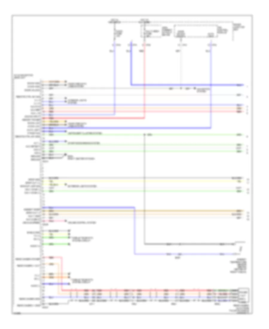
Navigation Wiring Diagram, with Amplifier (1 of 3) for Hyundai Veloster 2014
List of elements for Navigation Wiring Diagram, with Amplifier (1 of 3) for Hyundai Veloster 2014:
- A/v & navigation head unit
- Acc/on input
- Alt l
- Ambient snsr
- Ambient temperature sensor (behind center of front fascia)
- Audio (+)
- Audio (-)
- Audio fuse 10a
- Auto light
- Aux cusb in
- Aux detect
- Aux l in
- Aux r in
- Aux ref
- Aux v gnd
- B-can high
- B-can low
- Backup lamp sig
- Computer data lines system
- Cruise control system
- Door unlock
- Door unlock switch
- Em61
- Exterior lights system
- Fr21
- Gm04 (right center of dash)
- Ground
- Hot at all times
- Hot in acc or on
- I/p-c
- I/p-d
- I/p-e
- I/p-g
- I/p-k
- Ill (+)
- Ill (-)
- Instrument cluster system
- Interior lights system
- Ips control module
- Leak current autocut device
- M-can high
- M-can low
- M02-a
- M02-b
- M02-m
- Memory power
- Mf11
- Mic(+)
- Mic(-)
- Mobile telematic system circuit
- Multi media fuse 15a
- Navi voice (+)
- Navi voice (-)
- Navigation system
- Nca gnd 2
- Nca power
- Nca v gnd
- Nca v out
- P position
- Pnk
- Rear camera (in outside tailgate handle assembly)
- Rear camera gnd
- Rear camera power
- Rear camera v gnd
- Rear camera v out
- Red
- Remote ctrl sw gnd
- Remote ctrl sw sig
- Rr01
- Rr02
- Rx (+)
- Rx (-)
- Shield gnd
- Smart junction box
- Spdif gnd
- Spdif out (+)
- Spdif out (-)
- Starting/charging system
- Tx (+)
- Tx (-)
- Vehicle speed
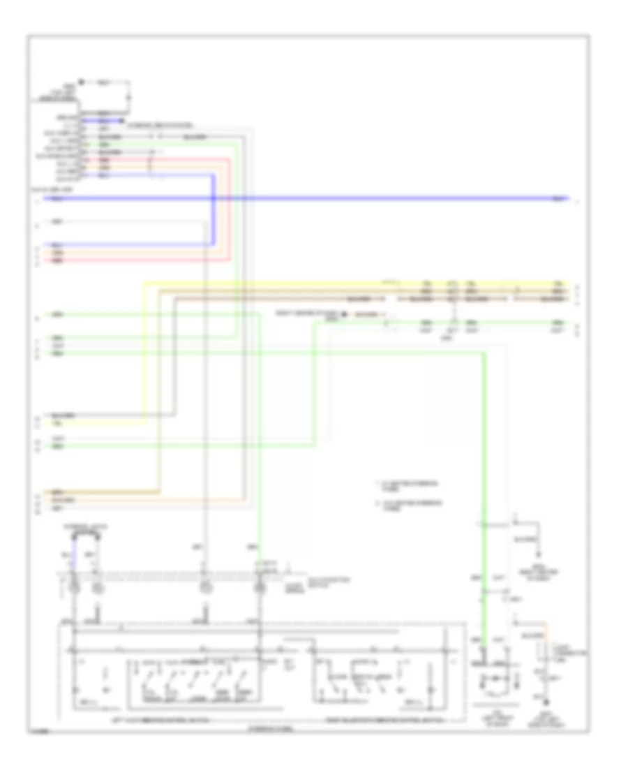
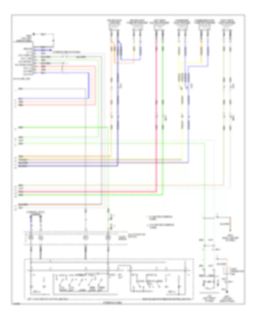
Navigation Wiring Diagram, with Amplifier (2 of 3) for Hyundai Veloster 2014
List of elements for Navigation Wiring Diagram, with Amplifier (2 of 3) for Hyundai Veloster 2014:
- (+)
- (-)
- (right center of dash) gm04
- 3ea ill
- 4ea ill
- Audio
- Audio (+)
- Audio (-)
- Aux & usb jack
- Aux detect
- Aux l in
- Aux r in
- Aux ref
- Aux shield gnd
- Aux v gnd
- Aux video in
- B/t
- B/t in
- Call
- Clock spring
- Down
- End of
- Gm01 (top left side of dash)
- Gm02 (top left side of dash)
- Gm04 (right center of dash)
- Ground
- Ill (+)
- Interior lights system
- Joint connector
- Left audio remote control switch
- M01-h
- M01-r
- Mf61
- Mic (+)
- Mic (-)
- Mic (left front of roof)
- Mode
- Mr11
- Multi-function switch
- Nca
- Out
- Red
- Seek
- Send
- Steering wheel
- Ura
- Voice
- Vol
- W/ heated steering wheel
- W/o heated steering
- Wheel
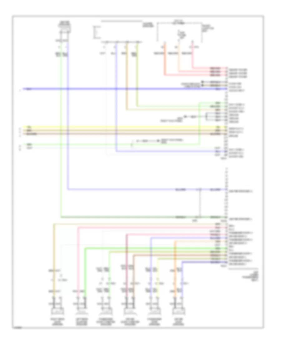
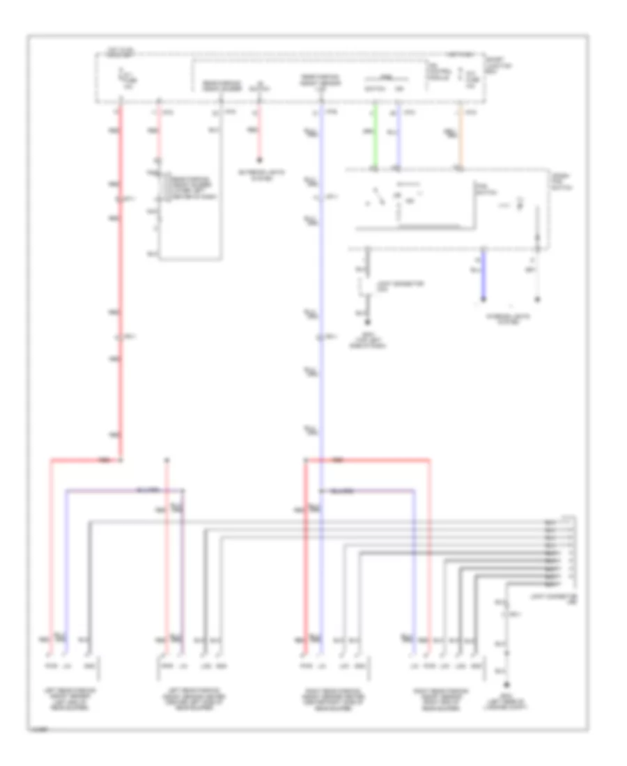
Navigation Wiring Diagram, with Amplifier (3 of 3) for Hyundai Veloster 2014
List of elements for Navigation Wiring Diagram, with Amplifier (3 of 3) for Hyundai Veloster 2014:
- (+)
- (-)
- (right kick panel) gf02
- Acc/on input
- Amp (under passenger's seat)
- Amp fuse 25a
- Center speaker
- Center speaker (+)
- Center speaker (-)
- Computer data
- Driver door (+)
- Driver door (-)
- Driver door speaker
- Driver door tweeter speaker
- F02-a
- F02-b
- F02-c
- Fd11
- Fd21
- Fd41
- Gf02 (right kick panel)
- Ground
- Hot at all times
- I/p-k
- Left rear quarter speaker
- Lines system
- M-can high
- M-can low
- Memory power
- Mf61
- Navi voice (+)
- Navi voice (-)
- Nca
- Passenger door (+)
- Passenger door (-)
- Passenger door speaker
- Passenger door tweeter speaker
- Pnk
- Right rear door speaker
- Rl(+)
- Rl(-)
- Rr(+)
- Rr(-)
- S/woof wl(+)
- S/woof wl(-)
- S/woof wr(+)
- S/woof wr(-)
- Smart junction box
- Spdif out (+)
- Spdif out (-)
- Woofer speaker
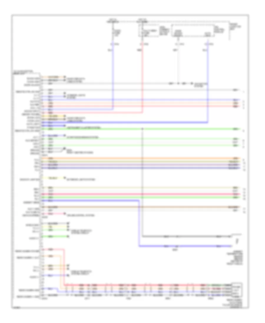
Navigation Wiring Diagram, without Amplifier (1 of 2) for Hyundai Veloster 2014
List of elements for Navigation Wiring Diagram, without Amplifier (1 of 2) for Hyundai Veloster 2014:
- A/v & navigation head unit
- Acc/on input
- Alt l
- Ambient sens
- Ambient temperature sensor (behind center of front fascia)
- Audio (+)
- Audio (-)
- Audio fuse 10a
- Auto light
- Aux cusb in
- Aux detect
- Aux l in
- Aux r in
- Aux ref
- Aux v gnd
- B-can high
- B-can low
- Backup lamp sig
- Computer data lines system
- Cruise control system
- Door unlock
- Door unlock switch
- Em61
- Exterior lights system
- Fl(+)
- Fl(-)
- Fr(+)
- Fr(-)
- Fr21
- Gm04 (right center of dash)
- Ground
- Hot at all times
- Hot in acc or on
- I/p-c
- I/p-d
- I/p-e
- I/p-g
- Ill (+)
- Ill (-)
- Instrument cluster system
- Interior lights system
- Ips control module
- Leak current autocut device
- M-can high
- M-can low
- M02-a
- M02-b
- M02-m
- Memory power
- Mf11
- Mic(+)
- Mic(-)
- Mobile telematic system circuit
- Multi media fuse 15a
- Navigation system
- Nca gnd 2
- Nca power
- Nca v gnd
- Nca v out
- P position
- Pnk
- Rear camera (in outside tailgate handle assembly)
- Rear camera gnd
- Rear camera power
- Rear camera v gnd
- Rear camera v out
- Red
- Remote ctrl sw gnd
- Remote ctrl sw sig
- Rl(+)
- Rl(-)
- Rr(+)
- Rr(-)
- Rr01
- Rr02
- Rx (+)
- Rx (-)
- Shield gnd
- Smart junction box
- Starting/charging system
- Tx (+)
- Tx (-)
- Vehicle speed
Navigation Wiring Diagram, without Amplifier (2 of 2) for Hyundai Veloster 2014
List of elements for Navigation Wiring Diagram, without Amplifier (2 of 2) for Hyundai Veloster 2014:
- (+)
- (-)
- 3ea ill
- 4ea ill
- Audio
- Audio (+)
- Audio (-)
- Aux & usb jack
- Aux detect
- Aux l in
- Aux r in
- Aux ref
- Aux shield gnd
- Aux v gnd
- Aux video in
- B/t
- B/t in
- Call
- Clock spring
- Down
- Driver door speaker
- Driver door tweeter speaker
- End of
- Fd11
- Fd21
- Fd41
- Gm01 (top left side of dash)
- Gm02 (top left side of dash)
- Gm04 (right center of dash)
- Ground
- Ill (+)
- Interior lights system
- Joint connector
- Left audio remote control switch
- Left rear quater speaker
- M01-h
- M01-r
- Mf11
- Mf61
- Mic (+)
- Mic (-)
- Mic (left front of roof)
- Mode
- Mr11
- Multi-function switch
- Nca
- Out
- Passenger door speaker
- Passenger door tweeter speaker
- Pnk
- Red
- Right rear door speaker
- Seek
- Send
- Steering wheel
- Ura
- Voice
- Vol
- W/ heated steering wheel
- W/o heated steering
- Wheel
Parking Assistant Wiring Diagram for Hyundai Veloster 2014
List of elements for Parking Assistant Wiring Diagram for Hyundai Veloster 2014:
- "r" switch
- (lin)
- 10a
- Crash pad switch
- Exterior lights system
- Fr11
- Gf03 (left rear of luggage compt)
- Gm01 (top left side of dash)
- Gnd
- Hot in on
- Hot in on or start
- I/p-b
- I/p-d
- I/p-g
- Ig 1 fuse 10a
- Ig 2 fuse
- Ill
- Ind
- Interior lights system
- Ips control module
- Joint connector uma
- Joint connector urc
- Left rear parking assist sensor (left end of rear bumper)
- Left rear parking assist sensor center (center left side of rear bumper)
- Lid1
- Lid2
- Lin
- Mf11
- Nca
- Pas
- Pas switch
- Pwr
- Rear parking assist buzzer
- Rear parking assist buzzer (lower left center of dash)
- Rear parking assist sensor
- Red
- Right rear parking assist sensor (right end of rear bumper)
- Right rear parking assist sensor center (center right side of rear bumper)
- Smart junction box
- Switch