AIR CONDITIONING
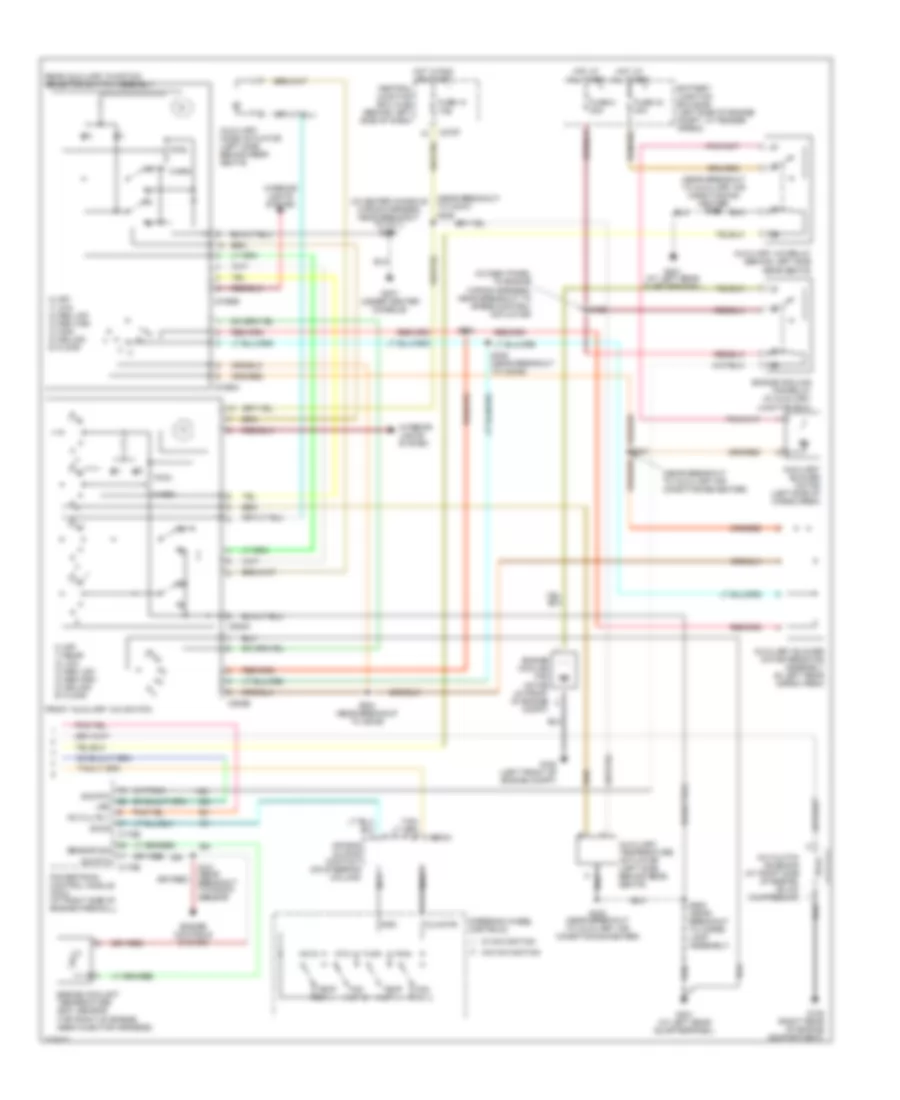
Automatic A/C Wiring Diagram (1 of 2) for Lincoln Aviator 2004

List of elements for Automatic A/C Wiring Diagram (1 of 2) for Lincoln Aviator 2004:
- (in main wiring harness, near breakout to c219)
- (near breakout to c238)
- A/c clutch relay
- A/c indicator clutch diode
- Act pot +5v
- Act pot -
- Act pot wiper
- Amb temp
- Ambient air temperature sensor (right front of engine compt, near radiator support)
- Battery junction box (bjb) (left side of engine compt, at fender apron)
- Blower ctrl rly
- Blower motor relay
- C220a
- C228a
- C228b
- C270a
- C270b
- C270d
- C3008e
- Central junction box (cjb) (behind left side of dash)
- Central security module (csm) (behind right rear seat)
- Cluster power
- Computer data lines system
- Control sw
- Defogger system
- Dual automatic temperature control (datc) module (behind left side of dash)
- Front blower motor (behind center of dash)
- Front blower motor speed controller (behind center of dash)
- Fuse 10 10a
- Fuse 15 10a
- Fuse 2 10a
- Fuse 30 5a
- Fuse 36 40a
- Fuse 37 15a
- G107 (left side of engine compartment)
- G200 (behind right kick panel)
- G203 (under center console)
- Gnd
- Ground
- Hbr switch in
- Hot at all times
- Hot in run or start
- Ign run/start
- Illumination
- In car temp
- In-vehicle temperature sensor (on left side of dash)
- Inboard instrument cluster
- Interior lights system
- J/c 1
- J/c 2
- Left temperature blend door actuator (behind right side of dash)
- Microprocessor
- Motor
- Motor drv 1
- Motor drv 2
- Pass mtr 1
- Pass mtr 2
- R def out
- R def switch
- Remote solenoid assembly (behind center of dash)
- Right temperature blend door actuator (behind right side of dash)
- Rs gnd
- Rs1
- Rs2
- Rs3
- Rs4
- Rs5
- S201
- S202
- S218 (in main wiring harness, near breakout to c211)
- S219
- S223 (in main wiring harness, near breakout to audio unit)
- S423
- Scp +
- Scp -
- Sens gnd
- Sun load l
- Sun load r
- Sun load sens
- Sunload sensor (at top center of dash)
- To passenger side impact sensor 1)
- Var speed in
- Vbatt
- Vbc fb
- Vbc hbr
- Vbc out
Automatic A/C Wiring Diagram (2 of 2) for Lincoln Aviator 2004
List of elements for Automatic A/C Wiring Diagram (2 of 2) for Lincoln Aviator 2004:
- (in center console wiring harness, near breakout to c311) s308
- (in dash panel to engine wiring harness, near breakout to speed control actuator)
- (near breakout to auxiliary air conditioning/ heater) s302
- (near breakout to auxiliary air conditioning/heater)
- (near breakout to c3047) s306
- (top right of engine, near injector harness)
- 0) off 1) low 2) med low 3) med high 4) high 5) ceiling 6) floor
- 0) off 1) rear 2) low 3) med low 4) med high 5) ceiling 6) floor
- A/c clu rly
- A/c clutch solenoid (at right side of engine, on a/c
- Air bag sliding contact (on steering column)
- Auxiliary a/c relay (behind left side rear seats)
- Auxiliary blower motor (left side of cargo area)
- Auxiliary blower motor resistor assembly (in left rear cargo area)
- Auxiliary mode actuator (left side, behind rear seats)
- Auxiliary temperature actuator (left side, behind rear seats)
- Battery junction box (bjb) (left side of engine compt, at fender apron)
- C175b
- C175e
- C218a
- C270f
- C3198a
- C3198b
- C938a
- C938b
- Central junction box (cjb) (behind left side of dash)
- Climate
- Compressor)
- Cool
- Engine controls system
- Engine coolant temperature (ect) sensor
- Engine cooling fan motor (in front of engine compt)
- Engine cooling fan relay (in auxiliary junction box)
- Fan dn
- Fan up
- Front auxiliary a/c switch
- Fuse 10 10a
- Fuse 33 30a
- Fuse 8 20a
- G105 (left front of engine compt)
- G108 (right rear of engine compartment)
- G207 (under center console)
- G401 (at left rear quarterpanel)
- Gnd
- Hot at all times
- Hot in run or start
- Interior lights system
- Led
- Nca
- Powertrain control module (pcm) (at right side of engine firewall)
- Rear auxiliary function selector switch assembly
- S126
- S141 (near breakout to knock sensor)
- S302 (near breakout to auxiliary air conditioning/heater)
- S303
- S304 (near breakout to c3049)
- S305 (near breakout to c3049)
- S905 (near breakout to cargo lamp assembly)
- Sccs
- Sensor sig
- Sig rtn
- Steering wheel controls
- Temp dn
- Temp up
- W/ navigation
- W/o navigation
- Warm