POWER DISTRIBUTION
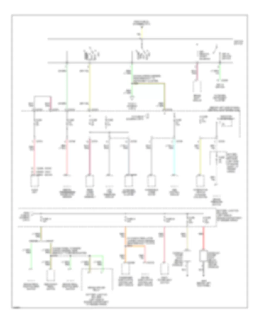
Power Distribution Wiring Diagram (1 of 4) for Lincoln Aviator 2004

List of elements for Power Distribution Wiring Diagram (1 of 4) for Lincoln Aviator 2004:
- (at right rear quarterpanel)
- (in dash panel to engine wiring harness, near breakout to battery junction box) s129
- (in main wiring harness, near breakout to instrument cluster) s213
- (in right rear of cargo area)
- (left side of engine compartment, at fender apron) battery junction box (bjb)
- (near battery junction box) s101
- (near battery junction box) s102
- (near battery junction box) s103
- (near breakout to main body wiring) s419
- Abs control module
- Accessory delay circuit breaker 30a
- Auxiliary a/c relay
- Auxiliary junction box (ajb) (right side of engine compt, at fender apron)
- Battery
- Battery junction box (bjb) (left side of engine compartment, at fender apron)
- Battery junction box (bjb) (left side of engine compt, at fender apron)
- Blower motor relay
- C102a
- C1035a
- C1035b
- C205a
- C270c
- C281b
- C3008e
- Central junction box (cjb) (behind left side of dash)
- Central security module (csm)
- Charge relay
- Daytime running lamps (drl) module
- Four wheel drive control module
- From fuse 19 (diagram 1 of 4)
- From fuse 6 (diagram 1 of 4)
- From s111 (diagram 4 of 4)
- Fuel pump relay
- Fuse 20a
- Fuse 30a
- Fuse 40a
- Fuse 50a
- Fuse 60a
- Fuse open
- G107 (left side of engine compt)
- G402
- Generator
- Horn relay
- Ignition relay
- Joint connector 1 (in bjb)
- Left front power window motor
- Left hid headlamp relay
- Left turn trailer tow relay
- Main light switch
- Pcm relay
- Rear auxiliary junction box
- Rear auxiliary junction box (in right rear of cargo area)
- Rear window defrost relay
- Rear wiper motor assembly
- Red
- Right hid headlamp relay
- Right rear power point
- Right turn
- Starter motor
- Starter motor relay
- To accessory delay relay (diagram 3 of 4)
- To fuse 10 (diagram 3 of 4)
- To fuse 11 (diagram 1 of 4)
- To fuse 15 (diagram 3 of 4)
- To fuse 16 (diagram 4 of 4)
- To fuse 26 (diagram 1 of 4)
- To fuse 5 (diagram 3 of 4)
- To ignition switch (diagram 2 of 4)
- Trailer electronic brake control module
- Trailer tow battery
- Trailer tow parking lamp relay
- Trailer tow relay
- Trailer tow reversing lamps relay
- Windshield wiper motor
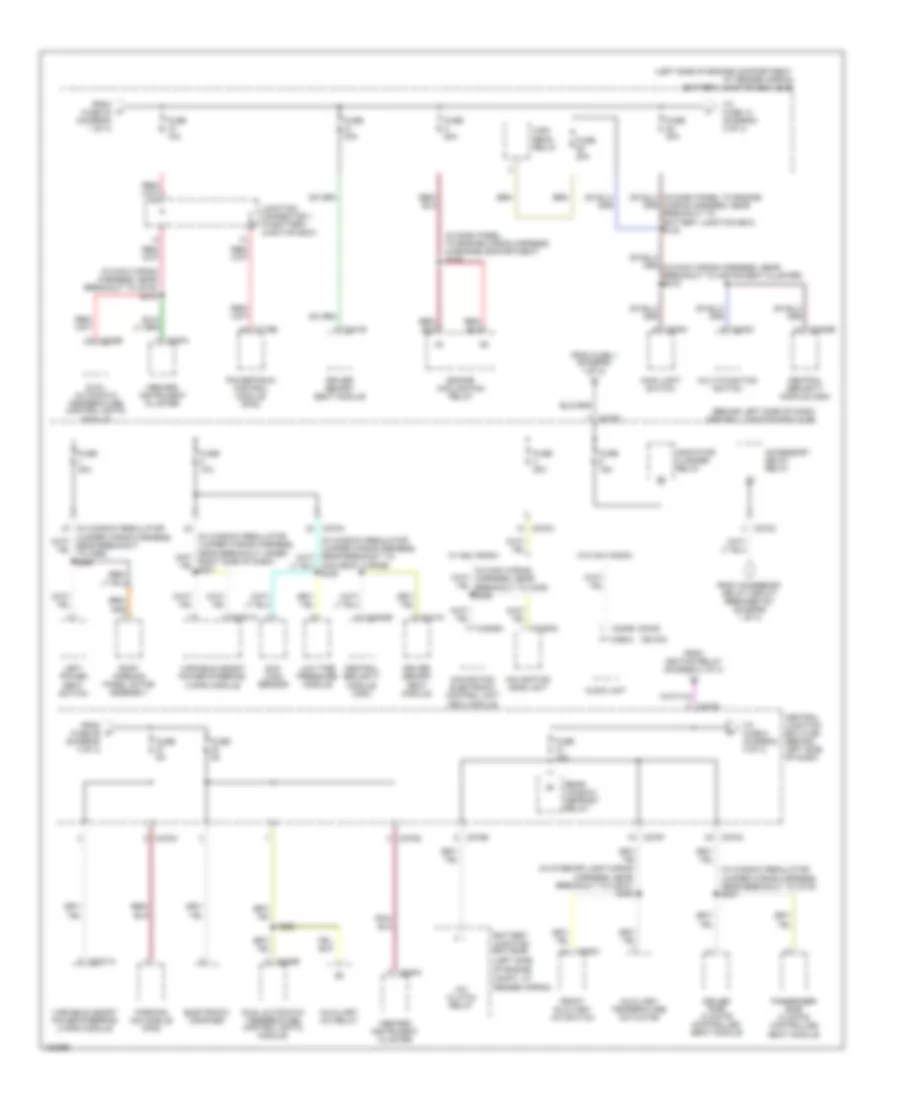
Power Distribution Wiring Diagram (2 of 4) for Lincoln Aviator 2004
List of elements for Power Distribution Wiring Diagram (2 of 4) for Lincoln Aviator 2004:
- (behind left side of dash) central junction box (cjb)
- (cdx6)
- (dm100)
- (in dash panel to engine wiring harness, near breakout to brake booster) s109
- (in main wiring harness, near breakout to instrument cluster) s229
- (in window regulator jumper wiring harness, near breakout to c315) s343
- (left side
- (nav)
- Abs control module
- Acc
- Audio unit
- Battery junction box (bjb)
- Battery junction box (bjb) (left side of engine compartment, at fender apron)
- Brake pedal position (bpp) switch
- Brake pressure switch
- Brake shift module
- C220b
- C2253c
- C240b
- C270a
- C270b
- C270d
- C270e
- C270f
- C270g
- C270h
- C290a
- C3031b
- C3036b
- Console 2 power point (below rear of center console)
- Console power point (below center console)
- Digital digital transmission transmission range (dtr) sensor
- Driver side climate controlled seat module
- Dynamics (ivd) switch
- From fuse 22 (diagram 3 of 4)
- From fuse 23 (diagram 1 of 4)
- Fuse 10a
- Fuse 14 15a
- Fuse 20a
- Fuse 2a
- Fuse 31 30a
- Fuse 32 30a
- Fuse 5a
- G205 (behind left kick panel)
- Ignition switch
- Indicator flasher relay
- Interactive vehicle
- Key in ignition
- Key in ignition switch
- Key removal inhibit solenoid
- Lock
- Low tire pressure module
- Of engine compt, at fender apron)
- Off
- Outboard instrument cluster
- Passenger side climate controlled seat module
- Rear wiper motor assembly
- Red
- Redundant pedal switch
- Right power seat switch
- Run
- Start
- To fuse 25 (diagram 4 of 4)
- To s111 (diagram 4 of 4)
- W/ ivd
- W/o ivd
- Windshield wiper motor
Power Distribution Wiring Diagram (3 of 4) for Lincoln Aviator 2004
List of elements for Power Distribution Wiring Diagram (3 of 4) for Lincoln Aviator 2004:
- (behind left side of dash) central junction box (cjb)
- (cdx6)
- (dm100)
- (in dash panel to engine wiring harness, in engine compartment) s126
- (in interior lamp wiring harness, near breakout to c3047) s306
- (in main wiring harness, near breakout to c219) s219
- (in window regulator jumper wiring harness, near breakout to c315) s337
- (left side
- (left side of engine compartment, at fender apron) battery junction box (bjb)
- A/c clutch relay
- Accessory delay relay
- Audio unit
- Auxiliary a/c relay
- Auxiliary temperature actuator
- Battery junction box (bjb)
- C175b
- C202c
- C205a
- C220a
- C2231a
- C2253c
- C228b
- C240b
- C270a
- C270b
- C270c
- C270d
- C270f
- C270h
- C290a
- C3008e
- C341e
- C341g
- C4209a
- C938a
- Central junction box (cjb) (behind left side of dash)
- Central security module (csm)
- Driver memory seat module
- Driver side climate controlled seat module
- Dual automatic temperature control (datc) module
- Electronic compass
- Engine cooling fan relay
- From accessory delay circuit breaker 401 (diagram 1 of 4)
- From fuse 1 (diagram 1 of 4)
- From fuse 23 (diagram 1 of 4)
- From fuse 26 (diagram 4 of 4)
- From ignition relay (diagram 1 of 4)
- Front auxiliary a/c switch
- Fuse 10a
- Fuse 15a
- Fuse 20a
- Fuse 30a
- Fuse 5a
- High beam relay
- Inboard instrument cluster
- Indicator flasher relay
- Junction connector 1 (in battery junction box)
- Left power seat switch
- Low tire pressure module
- Main body wiring) s335
- Main light switch
- Multi-function switch
- Navigation electronic control unit (ecu) module
- Navigation head unit
- Of engine compt, at fender apron)
- Parking aid module (pam)
- Passenger side climate controlled seat module
- Powertrain control module (pcm)
- Rear window defrost relay
- Roof opening panel motor assembly
- S223
- Sun load sensor
- To fuse 14 (diagram 2 of 4)
- To fuse 8 (diagram 4 of 4)
- Variable assist power steering (vaps) module
- W/ nav radio
- W/o nav radio
- Wiring harness, near breakout to battery junction box) s130
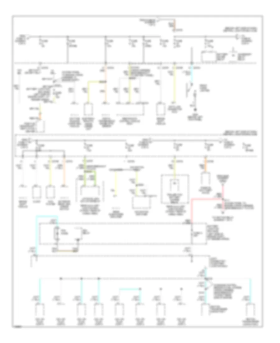
Power Distribution Wiring Diagram (4 of 4) for Lincoln Aviator 2004
List of elements for Power Distribution Wiring Diagram (4 of 4) for Lincoln Aviator 2004:
- (behind left side of dash) central junction box (cjb)
- (in dash panel to engine wiring harness, in engine compt)
- (in engine control sensor & fuel charge wiring harness, near breakout to right rear side of engine)
- (in main
- Accessory delay relay
- Battery junction box (bjb) (left side of engine compt, at fender apron)
- Battery saver relay
- Brake shift module
- C270a
- C270c
- C270e
- C270f
- C270g
- C310a
- C4211a
- Cdx6 radio
- Clock
- Coil on plug (cop) 1
- Coil on plug (cop) 2
- Coil on plug (cop) 3
- Coil on plug (cop) 4
- Coil on plug (cop) 5
- Coil on plug (cop) 6
- Coil on plug (cop) 7
- Coil on plug (cop) 8
- Data link connector (dlc)
- Daytime running lamps (drl) module
- Digital transmission range (dtr) sensor
- Dvd player
- Eletroch- romatic inside mirror unit
- Exterior rear view mirror switch
- From fuse 17 (diagram 4 of 4)
- From fuse 22 (diagram 2 of 4)
- From fuse 29 f (diagram 1 of 4)
- From k fuse 10 (diagram 3 of 4)
- From s229 (diagram 2 of 4)
- Front cigar lighter
- Fuse 10a
- Fuse 15a
- Fuse 20a
- Fuse 30a
- Fuse 41 25a
- Fuse 5a
- Fuse 7.5a
- Fuse open
- Fuse spare
- G205 (behind left kick panel)
- Ignition transformer capacitor 1
- Ignition transformer capacitor 2
- Joint connector 1 (in battery junction box)
- Liftgate lock actuator relay
- Navigation amplifier
- Navigation radio
- Passive anti-theft (pats)
- Pcm diode
- Pcm relay
- Positive crankshaft ventilation heater
- Rear auxiliary junction box (in right rear of cargo area)
- Rear subwoofer amplifier
- Restraints control module (rcm)
- S111 (in dash panel to engine wiring harness, near breakout to c133)
- S138
- S143
- S228
- S232
- To fuse 20 (diagram 4 of 4)
- To fuse 27 (diagram 3 of 4)
- To ignition relay (diagram 1 of 4)
- Trailer tow battery charge relay
- W/ drl
- W/o drl