SHIFT INTERLOCK
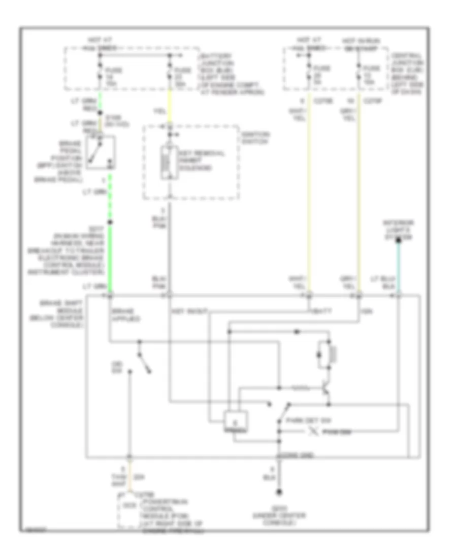
Shift Interlock Wiring Diagram for Lincoln Aviator 2004
List of elements for Shift Interlock Wiring Diagram for Lincoln Aviator 2004:
- All times
- Battery junction box (bjb) (left side of engine compt, at fender apron)
- Brake pedal position (bpp) switch (above brake pedal)
- Brake shift module (below center console)
- C175b
- C270e
- C270f
- Central junction box (cjb) (behind left side of dash)
- Cons gnd
- E prndl
- Fuse 10a
- Fuse 15a
- Fuse 30a
- Fuse 5a
- G203 (under center console)
- Hot at
- Hot in run
- Ign
- Ignition switch
- Interior lights system
- Key in/out
- Key removal inhibit solenoid
- O/d sw
- Ocs
- Or start
- Park det sw
- Powertrain control module (pcm) (at right side of engine firewall)
- Pwm dim
- Red
- S109
- S217 (in main wiring harness, near breakout to trailer electronic brake control module) instrument cluster)
- Tan/
- Vbatt
 English