
HORN
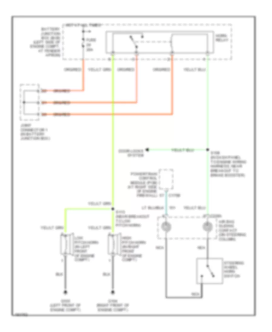
Horn Wiring Diagram for Lincoln Aviator 2004
List of elements for Horn Wiring Diagram for Lincoln Aviator 2004:
AIR CONDITIONINGANTI-LOCK BRAKESANTI-THEFTCOOLING FANCOMPUTER DATA LINESDEFOGGERSCRUISE CONTROLELECTRONIC POWER STEERINGENGINE PERFORMANCEEXTERIOR LIGHTSNAVIGATIONGROUND DISTRIBUTIONHEADLIGHTSHORNINTERIOR LIGHTSMEMORY SYSTEMSPOWER MIRRORSPOWER DISTRIBUTIONPOWER DOOR LOCKSPOWER WINDOWSINSTRUMENT CLUSTERRADIOPOWER SEATSPOWER TOP/SUNROOFSTARTING/CHARGINGTRANSMISSIONSUPPLEMENTAL RESTRAINTSSHIFT INTERLOCKWIPER/WASHERWARNING SYSTEMS