AIR CONDITIONING
A/C Wiring Diagram for Ford Aerostar 1996

List of elements for A/C Wiring Diagram for Ford Aerostar 1996:
- (3.0l)
- (4.0l)
- (right rear of engine compartment on a/c accumulator)
- (top left center of safety wall)
- (top rear corner of right fender apron)
- (top rear corner of right fender apron) g121
- A/c clutch diode
- A/c control assembly
- A/c clutch field coil
- A/c cutout relay (in engine compartment relay box )
- Auxiliary a/c system refrigerant valve solenoid (behind left b pillar)
- Auxiliary blower motor
- Auxiliary blower motor resistor assembly (behind left b pillar)
- Auxiliary power relay (behind left b pillar)
- Blower motor
- Blower motor resistor assembly (top right side of safety wall)
- Clutch cycling pressure switch
- Def
- Defrost
- Floor
- Front auxiliary blower motor switch
- Fuse 6 20a
- Fuse 9 30a
- Fuse panel
- G105
- G206 (behind center of i/p, left of radio)
- Heat
- High pressure cutoff switch (3.0l-right front of engine) (4.0l-left front of engine)
- Hot at all times
- Hot in accy or run
- Hot in run
- Main blower motor switch
- Max
- Med
- Mix
- Norm
- Off
- Pcm power relay
- Power- train control module (top left side of safety wall)
- Rear
- Rear auxiliary blower motor switch
- Red
- Vent
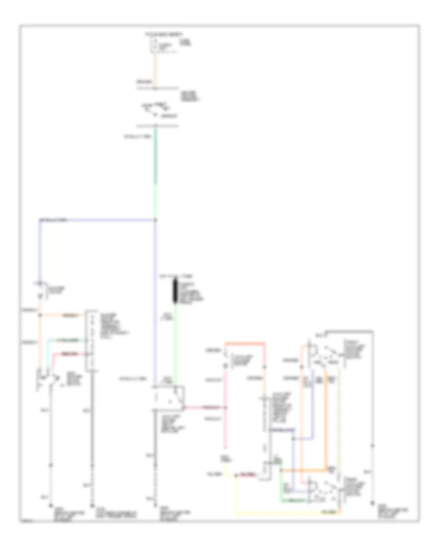
Heater Wiring Diagram for Ford Aerostar 1996
List of elements for Heater Wiring Diagram for Ford Aerostar 1996:
- (not used)
- Auxiliary blower motor
- Auxiliary blower motor resistor assembly (behind left b pillar)
- Auxiliary power relay (behind left b pillar)
- Blower motor
- Blower motor resistor assembly (top right side of safety wall)
- Defrost
- Front auxiliary blower motor switch
- Fuse 9 30a
- Fuse panel
- G105 (top rear corner of right fender apron)
- G206 (behind center of i/p, left of radio)
- Heat
- Heater control assembly
- Hot at all times
- Hot in accy or run
- Main blower motor switch
- Med
- Mix
- Off
- Rear
- Rear auxiliary blower motor switch
- Vent
 English