SUPPLEMENTAL RESTRAINTS
Supplemental Restraint Wiring Diagram for Ford Aerostar 1996
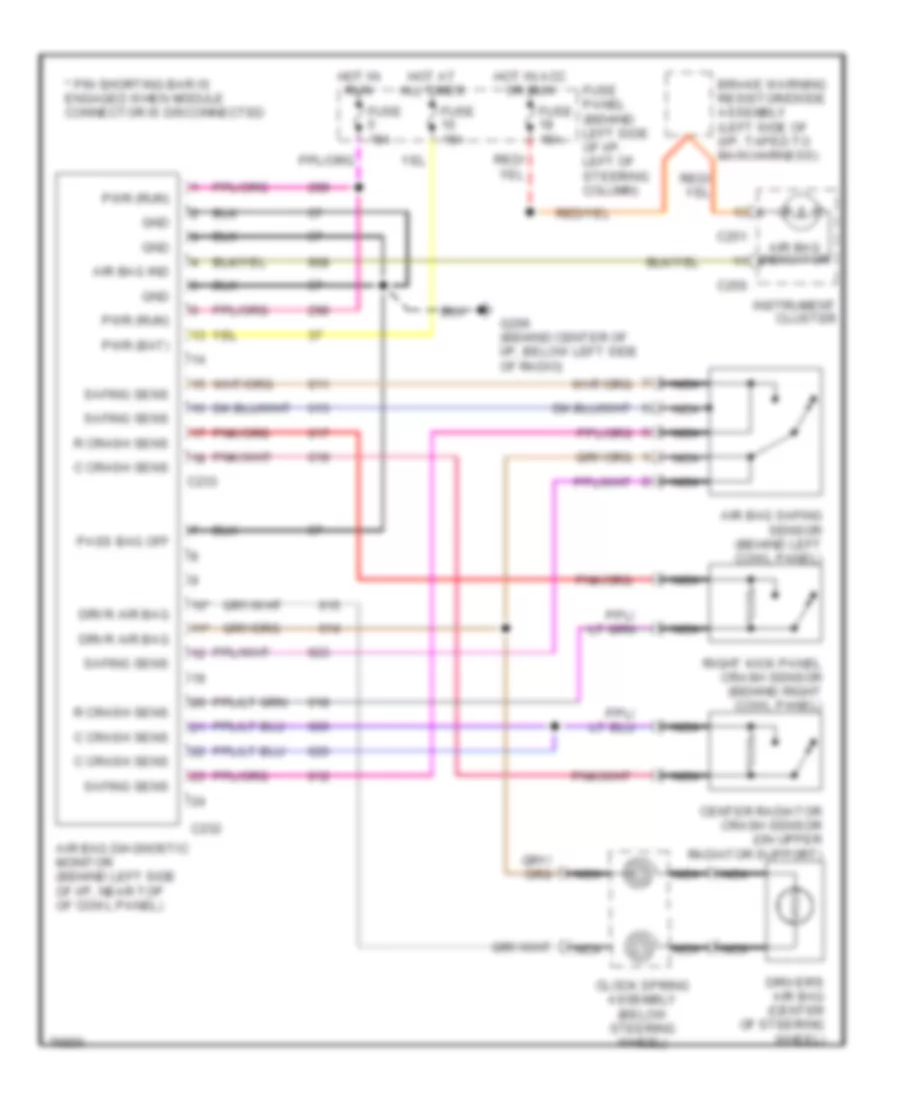
List of elements for Supplemental Restraint Wiring Diagram for Ford Aerostar 1996:
- * pin shorting bar is engaged when module connector is disconnected
- 10*
- 11*
- Air bag diagnostic monitor (behind left side of i/p, near top of cowl panel)
- Air bag ind
- Air bag indicator
- Air bag safing sensor (behind left cowl panel)
- Brake warning resistor/diode assembly (left side of (i/p, taped to main harness)
- C crash sens
- C232
- C233
- C250
- C251
- Center radiator crash sensor (on upper radiator support)
- Clock spring assembly (below steering wheel)
- Driver's air bag (center of steering wheel)
- Drvr air bag
- Fuse 15a
- Fuse panel (behind left side of i/p, left of steering column)
- G206 (behind center of i/p, below left side of radio)
- Gnd
- Hot at all times
- Hot in acc or run
- Hot in run
- Instrument cluster
- Nca
- Pass bag off
- Pwr (bat)
- Pwr (run)
- R crash sens
- Right kick panel crash sensor (behind right cowl panel)
- Safing sens
 English