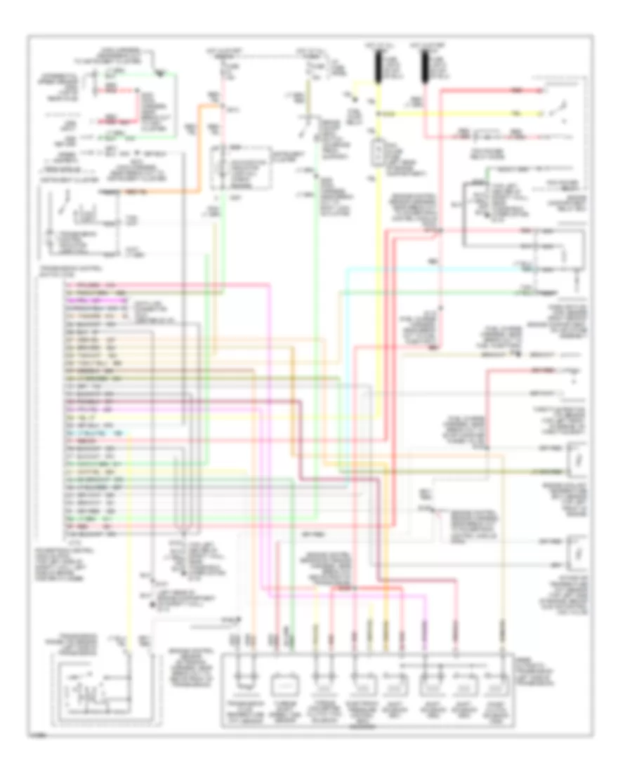
TRANSMISSION
3.0L
3.0L, Transmission Wiring Diagram for Ford Aerostar 1996

List of elements for 3.0L, Transmission Wiring Diagram for Ford Aerostar 1996:
- (engine control sensor extension harness, near break out above front of trans) s127
- (engine control sensor harness, near break out above power- train control module (pcm))
- (engine control sensor harness, near break out to powertrain control module (pcm)) s116
- (fuel charge harness, near break out to fuel injector 4) s123
- (left rear of engine compartment on safety wall) g114
- (main harness, near break out to instrument cluster)
- (top left center of safety wall, near windshield wiper motor) g116
- 4r44e automatic transmission (left side of transmission)
- Brake on/off (boo) switch (on brake pedal support)
- C172
- C251
- Coast clutch solenoid (css)
- Data link connector (dlc) (center of i/p)
- Differential speed sensor (dss) (top of rear axle)
- Dss input
- Dss return
- Electronic pressure control (epc) solenoid
- Engine compartment relay box
- Engine compt, taped to engine control sensor harness)
- Engine control extension harness, near break out above front of trans)
- Engine coolant temperature (ect) sensor (top center front of engine, above water pump pulley)
- Fuel pump relay
- Fuse 15a
- Hot at all times
- Hot in start or run
- I/p fuse panel
- Instrument cluster
- Intake air temperature (iat) sensor (top left side of engine, behind idle air control (iac) valve)
- Malfunction indicator lamp (mil) (check engine)
- Mass air flow (maf) sensor (right rear of engine compartment, on air intake assembly)
- N d
- Nca
- O/d off
- Pcm inline fuse (left rear of engine compartment)
- Pcm power relay
- Pcm power relay diode
- Powertrain control module (pcm) (top left side of safety wall, left side of brake master cylinder)
- Psom module
- Red
- Red/ pnk
- S107
- S115 (fuel charge harness, near break out to fuel injector 4)
- S119 (fuel charge harness, near break out to fuel injector 2)
- S122
- S124
- S125
- S126
- S128 (fuel charge harness, near break out to fuel injector 4)
- S213
- S228 (main harness, near break out to shift lock actuator)
- S231
- S232 (main harness, near break out to inst cluster)
- S273 (main harness, near break out to instrument cluster)
- Shift solenoid (ss1)
- Shift solenoid (ss2)
- Shift solenoid (ss3)
- Speed output
- Tach test conn (left rear of
- Throttle position (tp) sensor (top center front of engine, on throttle body)
- Torque converter clutch (tcc) solenoid
- Transmission control indicator lamp (tcil)
- Transmission control switch (tcs)
- Transmission fluid temperature (tft) sensor
- Transmission range (tr) sensor (left side of transmission)
- Turbine shaft speed (tss) sensor
4.0L
4.0L, 4R55E Transmission Wiring Diagram for Ford Aerostar 1996
List of elements for 4.0L, 4R55E Transmission Wiring Diagram for Ford Aerostar 1996:
- (engine control sensor extension harness, near break out above front of transmission) s127
- (engine control sensor extension harness, near break out to above front of transmission)
- (engine control sensor harness, near break out to powertrain control module (pcm))
- (engine control sensor harness, near break out to powertrain control module (pcm)) s116
- (fuel charge harness, near break out to evap canister purge valve) s128
- (fuel charge harness, near break out to fuel injector 6) s123
- (left rear of engine compartment on safety wall) g114
- (main harness, near break out to instrument cluster)
- (top left center of safety wall, near windshield wiper motor) g116
- 4r55e automatic transmission (left side of transmission)
- Brake on/off (boo) switch (on brake pedal support)
- C172
- C251
- Coast clutch solenoid (css)
- Data link connector (dlc) (center of i/p)
- Differential speed sensor (dss) (top of rear axle)
- Dss input
- Dss return
- Electronic pressure control (epc) solenoid
- Engine compartment relay box
- Engine coolant temperature (ect) sensor (top left front of engine)
- Fuel pump relay
- Fuse 15a
- Hot at all times
- Hot in start or run
- I/p fuse panel
- Instrument cluster
- Intake air temperature (iat) sensor (top left side of engine, behind idle air control (iac) valve)
- Malfunction indicator lamp (mil) (check engine)
- Mass air flow (maf) sensor (right rear of engine compartment, on air intake assembly)
- N d
- Nca
- O/d off
- Pcm inline fuse (left rear of engine compartment)
- Pcm power relay
- Pcm power relay diode
- Powertrain control module (pcm) (top left side of safety wall, left side of brake master cylinder)
- Psom module
- Red
- Red/ pnk
- S107
- S119 (fuel charge harness, near break out to fuel injector 3)
- S122
- S124
- S125
- S126
- S213
- S228 (main harness, near break out to shift lock actuator)
- S231
- S232 (main harness, near break out to inst cluster)
- S273 (main harness, near break out to instrument cluster)
- Shift solenoid (ss1)
- Shift solenoid (ss2)
- Shift solenoid (ss3)
- Speed output
- Throttle position (tp) sensor (top left front of engine, on throttle body)
- Torque converter clutch (tcc) solenoid
- Transmission control indicator lamp (tcil)
- Transmission control switch (tcs)
- Transmission fluid temperature (tft) sensor
- Transmission range (tr) sensor (left side of transmission)
- Turbine shaft speed (tss) sensor
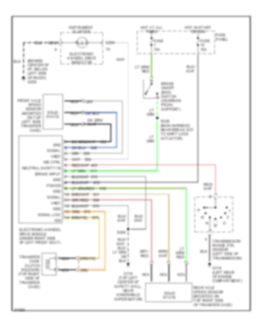
4.0L, Transfer Case Wiring Diagram for Ford Aerostar 1996
List of elements for 4.0L, Transfer Case Wiring Diagram for Ford Aerostar 1996:
- (behind center of i/p, below left side of radio) g206
- Brake input
- Brake on/off (boo) switch (on brake pedal support)
- C250
- Electronic 4 wheel drive indicator
- Electronic 4-wheel drive module (under right side of left front seat)
- Front axle speed sensor (mounted on top left side transfer case)
- Fuse 15a
- Fuse panel
- G114 (left rear of engine compartment)
- G116 (top left center of safety wall, near windshield wiper motor)
- Gnd
- Hot at all times
- Hot in start or run
- Ign
- Ind ctrl
- Instrument cluster
- Nca
- Neutral safety in
- Power
- Rear axle speed sensor (mounted on top right side of transfer case)
- S228 (main harness, near break out to shift lock actuator)
- S308
- Signal
- Signal low
- Solid state
- Transfer case clutch solenoid (top right side of transfer case)
- Transmission range (tr) sensor (left side of transmission)
- Vref