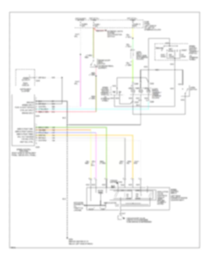
CRUISE CONTROL
Cruise Control Wiring Diagram for Ford Aerostar 1996
List of elements for Cruise Control Wiring Diagram for Ford Aerostar 1996:
- (behind center of i/p,
- (in steering wheel)
- (left rear corner of engine compartment)
- (on brake pedal support)
- 100-
- 40-
- 50,000 ohms
- Accel
- Actuator (connects to throttle linkage)
- Below left side of radio)
- Brake input
- Brake on/off (boo) switch
- C228
- C234
- C235
- C249
- C296
- Clock- spring assembly (inside steering column)
- Coast
- Ctrl sw input
- Exterior lights system (multi-function switch)
- Fast
- Fuse 1 15a
- Fuse 12 30a
- Fuse 6 20a
- Fuse panel (left side of i/p, left of steering column)
- G206
- Ground
- Horn relay (right side of steering column)
- Horn switch
- Hot at all
- Hot in accy
- Instrument cluster
- Nca
- Off
- Ohms
- Or run
- Pnk
- Psom module
- Pwr: in accy or run
- Red
- Resume
- Servo motor
- Servo posit feed
- Servo posit gnd
- Servo posit signal
- Set/
- Slow
- Sol volt source
- Sol+
- Speed control amplifier (right side of instrument panel, above cowl panel)
- Speed control servo
- Speed control switch assembly (partial)
- Speed input
- Speed output
- Times
- Vac
- Vac sol ctrl
- Vacuum distribution
- Vacuum dump valve (vents to atmosphere when brake is depressed)
- Vent
- Vent sol ctrl
 English