AIR CONDITIONING
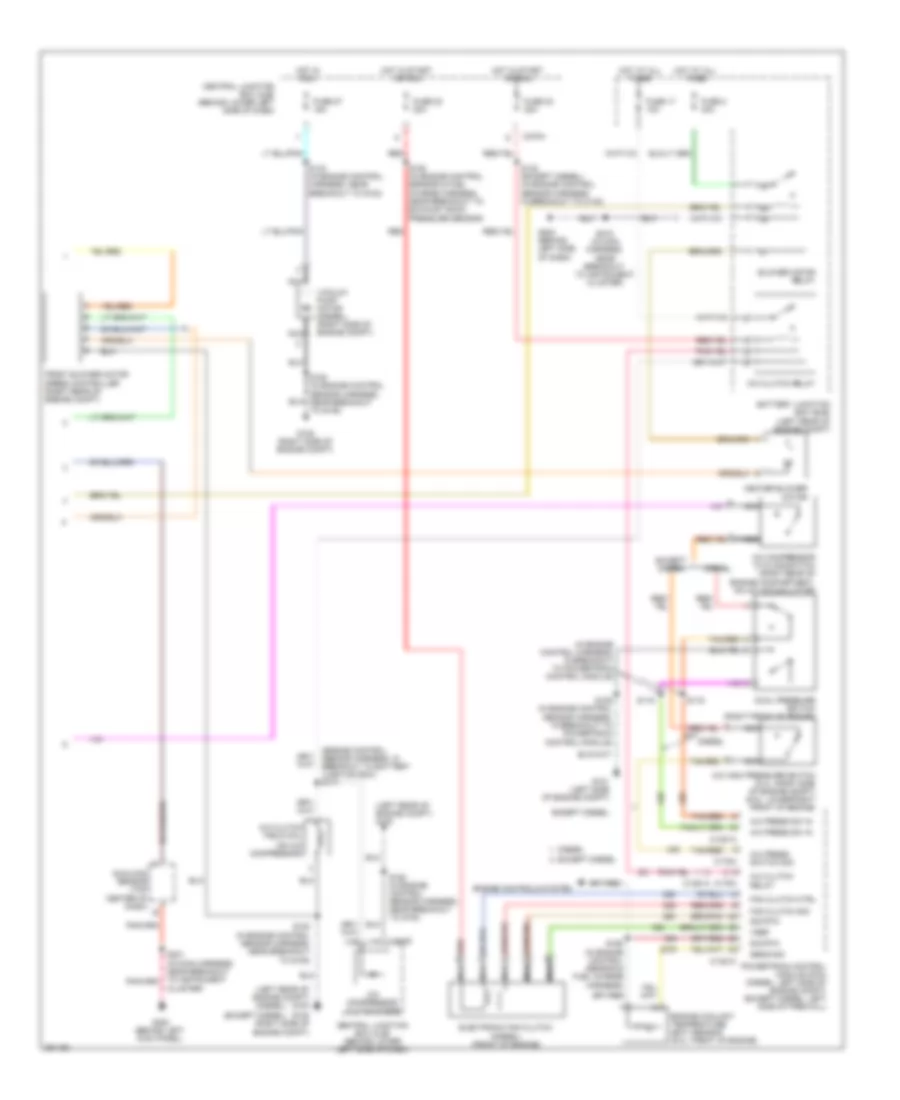
Automatic A/C Wiring Diagram (1 of 2) for Ford Cab & Chassis F350 Super Duty 2007

List of elements for Automatic A/C Wiring Diagram (1 of 2) for Ford Cab & Chassis F350 Super Duty 2007:
- A/c demand sig
- Air bag sliding contact (in steering column)
- Air temp dr sense +
- Air temp dr signal -
- Ambient air temperature sensor (except diesel: left front of engine compt)
- Ambient temp
- Blend door actuator +
- Blend door actuator -
- Blend door monitor
- Blower motor high
- Blower mtr rly ctrl
- Blower speed control signal return
- C228a
- C228b
- C270a
- Central junction box (cjb) (behind lower left side of dash)
- Computer data lines system
- Electronic automatic temperature control (eatc) module (behind center of dash)
- Fan speed (+)
- Fan speed (-)
- Fuse 10a
- Fuse 15a
- G202 (behind left side of dash)
- G300 (behind left kick panel)
- Harness, near breakout to instrument cluster)
- Hot at all times
- Hot in run
- Illumination
- In veh temp sensor
- In-vehicle temperature sensor (behind left side of dash)
- Interior lights system
- Logic gnd
- Nca
- Remote solenoid assembly (behind center of dash)
- Rest
- S148 (in main harness, near breakout to brake pressure transducer)
- S208 (in main harness, near breakout to instrument cluster)
- S218 (in main harness, near breakout to instrument cluster)
- S235 (in main harness, near breakout to auxiliary relay box 1)
- Sig return
- Solenoid 1 ctrl
- Solenoid 2 ctrl
- Solenoid 3 ctrl
- Solenoid 4 ctrl
- Solenoid 5 ctrl
- Solenoid assembly
- Speed controller
- Steering wheel controls
- Steering wheel radio switch
- Sunload sensor sig
- Temp (+)
- Temp (-)
- Temperature blend door actuator (behind right side of dash)
- Ubp diag
- Vpwr
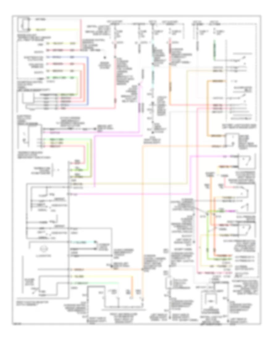
Automatic A/C Wiring Diagram (2 of 2) for Ford Cab & Chassis F350 Super Duty 2007
List of elements for Automatic A/C Wiring Diagram (2 of 2) for Ford Cab & Chassis F350 Super Duty 2007:
- (diesel)
- (engine control sensor harness, in breakout to battery junction box) s171
- (except diesel)
- (in engine control harness, in breakout to powertrain control module)
- (left rear of engine compt) g100
- (on a/c compressor)
- A/c clutch field coil
- A/c clutch relay
- A/c compressor clutch diode
- A/c compressor cycling switch (right rear of engine compartment, on a/c accumulator)
- A/c high pressure switch (5.4l: right side of engine compt) (6.8l: lower right front of engine)
- A/c press sw in
- A/c press switch sig
- Battery junction box (bjb) (left rear of engine compt)
- Blower motor relay
- C1381a
- C1381c
- C175a
- C270f
- C270h
- Central junction box (cjb) (behind lower left side of dash)
- Cluster)
- Diesel
- Dual pressure switch (right front of engine)
- Electronic fan clutch (diesel) (front of engine)
- Engine controls system
- Engine coolant temperature (ect) sensor (6.0l: front of engine)
- Except diesel
- Fan clutch ctrl
- Fan clutch sig
- Front blower motor speed controller (right rear of engine compt)
- Fuse 17 10a
- Fuse 2 40a
- Fuse 22 20a
- Fuse 23 20a
- Fuse 27 15a
- G101 (left side of engine compt)
- G108 (right side of engine compt)
- G202 (behind left side of dash)
- G300 (behind left kick panel)
- Heater blower motor
- Hot at all times
- Hot in run
- Hot in start or run
- Nca
- Powertrain control module (pcm) (diesel: left side of engine compt) (except diesel: left side of firewall)
- Red
- S106 (in engine control sensor harness, in breakout to powertrain control module)
- S116
- S119
- S122 (except diesel) (in engine control sensor harness, in breakout to c140)
- S124 (in engine control harness, near breakout to g100)
- S162 (in engine control sensor harness, near breakout to g100)
- S180 (in engine control sensor harness, near breakout to g108)
- S192 (in engine control sensor & fuel charge harness)
- S193 (in engine control sensor & fuel charge harness, near breakout to exhaust back pressure sensor)
- S218 (in main harness, near breakout to instrument cluster)
- Sens sig
- Sig rtn
- Sunload sensor (top center of dash)
- Tan/red
- Vacuum pump motor (diesel) (right side of engine compt)
- Vref
Manual A/C Wiring Diagram for Ford Cab & Chassis F350 Super Duty 2007
List of elements for Manual A/C Wiring Diagram for Ford Cab & Chassis F350 Super Duty 2007:
- (behind left side of dash) g201
- (diesel)
- (except diesel)
- (in engine control harness, in breakout to front heater blower motor resistor) s152
- (in engine control harness, in breakout to powertrain control module)
- (in engine control harness, near breakout to g100) s124
- (in engine control sensor & fuel charge harness) s192
- (in engine control sensor harness, in breakout to c140) (except diesel) s122
- (in main harness, near breakout to radio) s290
- (in main harness, near breakout to temperature blend door actuator) s257
- (left rear of engine compt) g100
- (left side of engine compt) g101
- (right side of engine compt) g108
- A/c clutch field coil (on a/c compressor)
- A/c clutch relay
- A/c compressor clutch diode
- A/c compressor cycling switch (right rear of engine compartment, on a/c accumulator)
- A/c high pressure switch (5.4l: right side of engine compt) (6.8l: lower right front of engine)
- A/c press sw in
- A/c press switch sig rtn
- Battery junction box (bjb) (left rear of engine compt)
- Blower motor relay
- Blower motor switch
- C1381a
- C1381c
- C175a
- C270a
- C270f
- C270h
- C289
- C294a
- C294b
- C294c
- Central junction box (cjb) (behind lower left side of dash)
- Cooling fan speed sig
- Defrost
- Diesel
- Dual pressure switch (right front of engine)
- Electronic fan clutch (diesel) (front of engine)
- Electronic fan clutch ctrl
- Engine controls system
- Engine coolant temperature (ect) sensor (6.0l: front of engine)
- Except diesel
- Floor
- Front function selector switch assembly
- Front heater blower motor resistor (right front of engine compt)
- Fuse 15a
- Fuse 17 10a
- Fuse 2 40a
- Fuse 20a
- Fuse 23 20a
- Fuse 27 15a
- G108 (right side of engine compt)
- Heater blower motor (right rear side of engine compt)
- High
- Hot at all times
- Hot in run
- Hot in start or run
- Illumination
- Interior lights system
- Low
- Max
- Med
- Mix
- Mode switch
- Nca
- Normal
- Off
- Powertrain control module (pcm) (diesel) (left side of engine compt)
- Powertrain control module (pcm) (diesel: left side of engine compt) (except diesel: left side of firewall)
- Red
- S106 (in engine control sensor harness, in breakout to powertrain control module)
- S116
- S119
- S162 (in engine control sensor harness, near breakout to g100)
- S180 (in engine control sensor harness, near breakout to g108)
- S193 (in engine control sensor & fuel charge harness, near breakout to exhaust back pressure sensor)
- S235 (in main harness, near breakout to auxiliary relay box 1)
- Sig rtn
- Tan/red
- Temperature blend door actuator (behind right side of dash)
- Temperature control potentiometer
- To g108)
- Vacuum pump motor (diesel) (right side of engine compt)
- Vent
- Vref