GROUND DISTRIBUTION
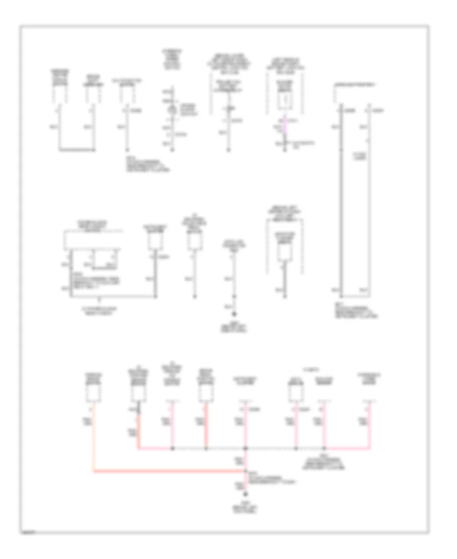
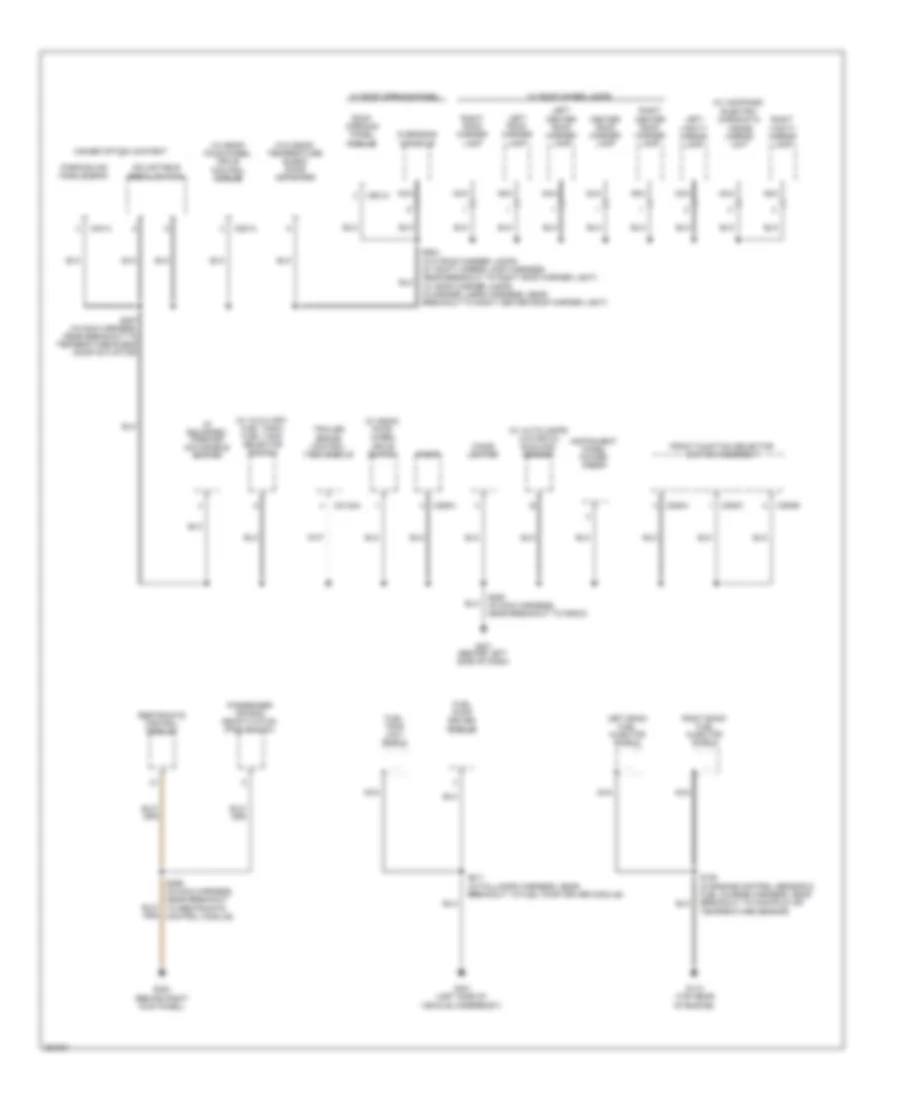
Ground Distribution Wiring Diagram (1 of 7) for Ford Cab & Chassis F350 Super Duty 2007

List of elements for Ground Distribution Wiring Diagram (1 of 7) for Ford Cab & Chassis F350 Super Duty 2007:
- (behind lower left side of dash) central junction box (cjb)
- (diesel)
- (diesel) a/c clutch field coil
- (diesel) air filter sensor
- (except diesel)
- (gasoline) a/c clutch field coil
- (if equipped) engine compart- ment lamp
- (if equipped) left front fog lamp
- (if equipped) right front fog lamp
- (left rear of engine compt) (w/ daytime running lamps) battery junction box (bjb)
- (left rear of engine compt) battery junction box (bjb)
- (left rear side of engine compt) auxiliary relay box 3
- 87a
- A/c compressor clutch diode
- Battery
- Battery 2
- Blower motor speed controller
- Brake fluid level switch
- C1021
- C1041
- C1284
- C1285
- C1381a
- C175b
- C270f
- Daytime running lamps (drl) relay 2
- Daytime running lamps (drl) relay 3
- Diesel
- Front heater blower motor resistor
- Fuel pump
- G100 (left rear of engine compt)
- G102 (diesel) (right front of engine compt) (except diesel) (right rear of engine compt)
- G104 (in engine compt, at right fender)
- G106 (at right frame rail, in engine compt)
- G108 (right side of engine compt)
- G109 (left side of engine)
- Gasoline
- Harness, near breakout to g108)
- Horn
- Htd mirror relay
- Left front park/ turn lamp
- Left front side lamp
- Left headlamp
- Left turn trailer tow relay
- Nca
- Parking lamp trailer tow relay
- Pcm power diode
- Pcm power relay
- Powertrain control module (pcm)
- Reversing lamps switch
- Right front park/ turn lamp
- Right front side lamp
- Right headlamp
- Right turn trailer tow relay
- S101 (in foglight jumper harness, near breakout to c1045)
- S102 (in engine control harness, under battery junction box)
- S117 (diesel) (in engine control harness, in breakout to powertrain control module)
- S250 (in back-up light switch to rear light feed har- ness, near breakout to auxiliary relay box 3)
- S250 (in back-up light switch to rear light feed harness, near breakout to auxiliary relay box 3)
- Transfer case high to low relay
- Transfer case low to high relay
- Upfitter relay
- Vacuum pump motor
- W/ eatc
- W/ esof
- W/ sealed beam headlamps
- W/o eatc
- W/o esof
- W/o sealed beam headlamps
- Windshield washer pump motor
- Windshield wiper motor
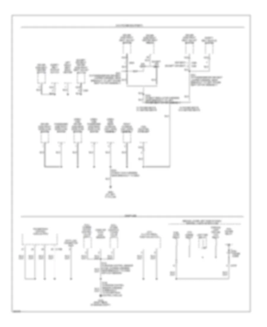
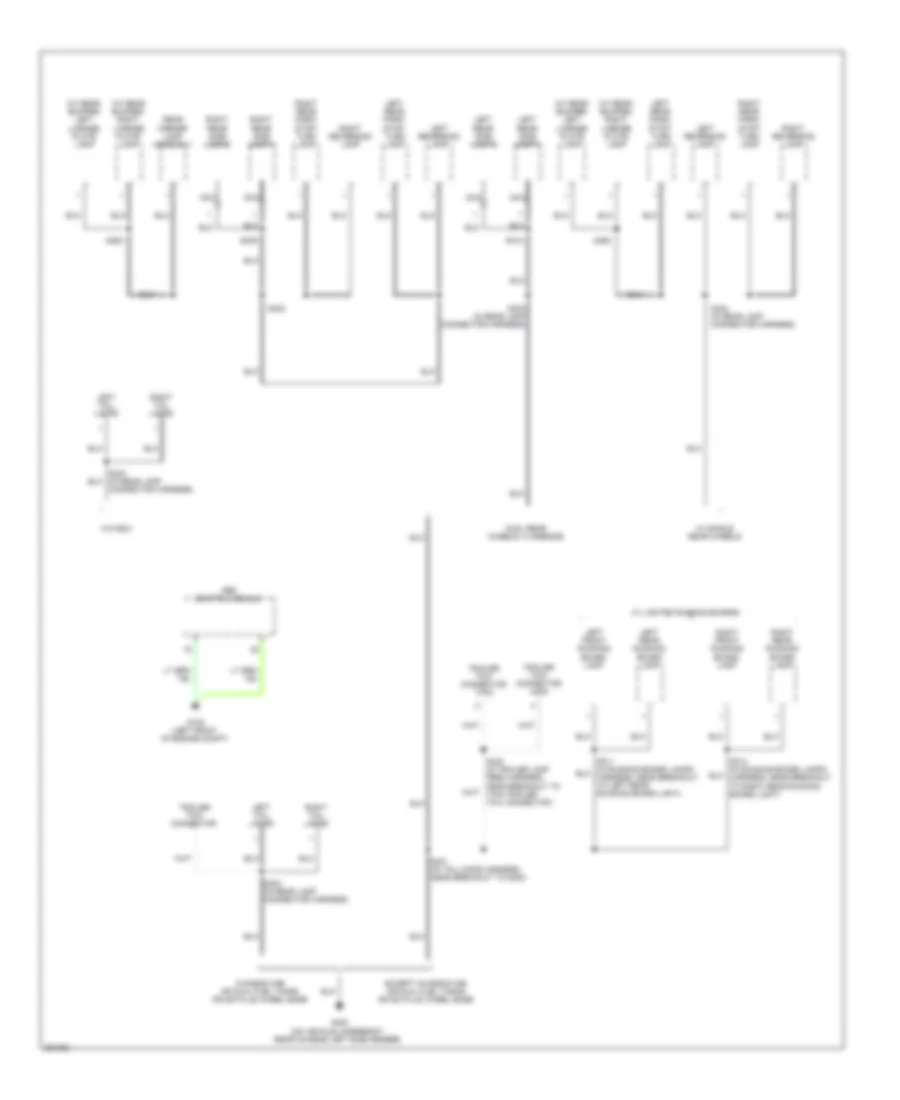
Ground Distribution Wiring Diagram (2 of 7) for Ford Cab & Chassis F350 Super Duty 2007
List of elements for Ground Distribution Wiring Diagram (2 of 7) for Ford Cab & Chassis F350 Super Duty 2007:
- (behind left center of dash) auxiliary relay box 1
- (behind lower left side of dash) (w/ power equipment) central junction box (cjb)
- (if equipped) adjustable pedal switch
- (if equipped) compass sensor module
- (if equipped) parking aid disable switch
- (left rear of engine compt) battery junction box (bjb)
- Air bag sliding contact
- Automatic a/c
- Blower motor relay
- Brake pedal position switch
- Brake shift interlock
- C1011
- C202b
- C205a
- C205b
- C218a
- C220a
- C220b
- C228a
- C270a
- Data link connector (dlc)
- Eatc module
- G202 (behind left side of dash)
- G300 (behind left kick panel)
- Indicator flasher relay
- Instrument cluster
- Main light switch
- Message center module switch
- Multifunction switch
- Nca
- Parking brake switch
- Power sliding rear window switch
- S201 (in main harness, near breakout to instrument cluster)
- S217 (in main harness, near breakout to instrument cluster)
- S218 (in main harness, near breakout to instrument cluster)
- S232 (in main harness, near breakout to auxiliary relay box 1)
- S278 (in main harness, near breakout to c291)
- Steering wheel/ speed control switch
- Sunload sensor
- Trailer tow battery charge relay
- W/ eatc
- W/ fog lamps
- W/ power sliding rear window
- Windshield wiper motor
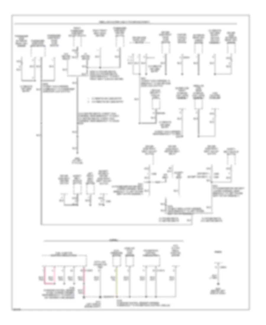
Ground Distribution Wiring Diagram (3 of 7) for Ford Cab & Chassis F350 Super Duty 2007
List of elements for Ground Distribution Wiring Diagram (3 of 7) for Ford Cab & Chassis F350 Super Duty 2007:
- (5.4l) charge motion control valve (cmcv)
- (6.8l) intake manifold tuning valve (imtv)
- (behind lower left side of dash) central junction box (cjb)
- (crew cab) driver side rear door ajar switch
- (crew cab) passenger side rear door ajar switch
- (crew cab) rear interior/ map lamps assembly
- (except sir seat)
- (except sir seat) driver side front seat adjust switch
- (gasoline)
- (m/t) clutch pedal position switch
- (sir seat)
- (w/o power equipment)
- C175b
- C270f
- C360
- C369
- Data link connector (dlc)
- Driver side front door ajar switch
- Driver side front heated seat relay
- Driver side front seat adjust switch
- Driver side seat heater switch
- Except sir seat
- Front interior/ map lamps assembly
- Fuel pump relay
- G102 (right rear of engine compt)
- G900 (at left "c" pillar)
- High mounted stoplamp
- Htd mirror relay
- Left front seat back heater
- Mass air flow (maf) sensor
- Nca
- Parking lamp trailer tow relay
- Passenger side front door ajar switch
- Pcm power diode
- Pcm power relay
- Powertrain control module (pcm)
- S106 (in engine control sensor harness, in breakout to powertrain control module)
- S300 (in body main harness, near breakout to g900)
- S301 (in passenger-driver seat jumper harness, near breakout to left power seat motor assembly)
- S332 (in seat regulator harness, near breakout to left power seat motor assembly)
- Safety belt buckle switch
- Sir seat
- Upfitter relay
- W/ power seats, w/ heated seats
- W/ power seats, w/o heated seats
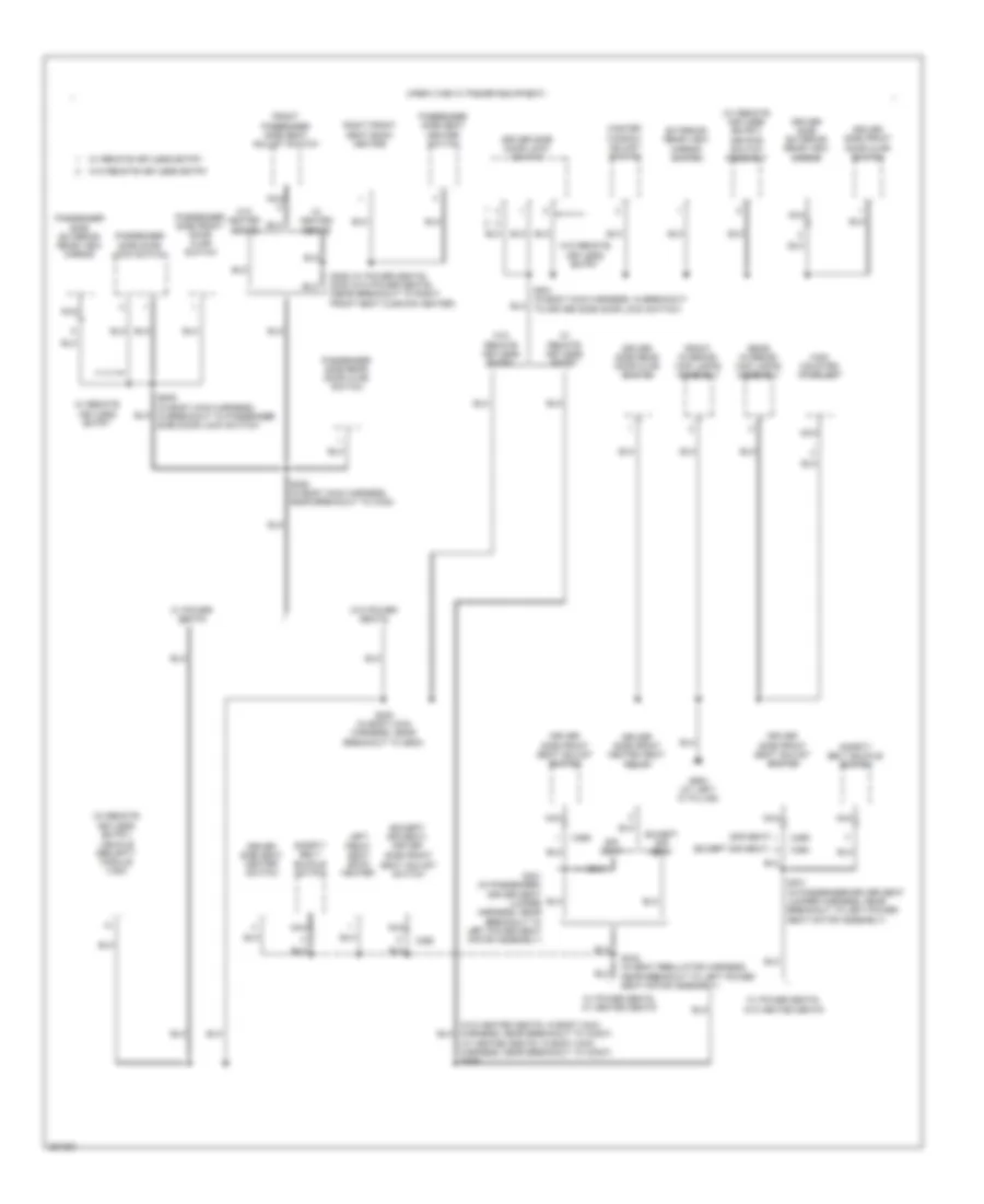
Ground Distribution Wiring Diagram (4 of 7) for Ford Cab & Chassis F350 Super Duty 2007
List of elements for Ground Distribution Wiring Diagram (4 of 7) for Ford Cab & Chassis F350 Super Duty 2007:
- (diesel)
- (except sir seat)
- (except sir seat) driver side front seat adjust switch
- (in body main harness, near breakout to g900) s300
- (m/t) clutch pedal position switch
- (regular & super cab w/ power equipment)
- (regular cab) rear interior/ map lamps assembly
- (sir seat)
- (super cab) front interior/ map lamps assembly
- (w/ remote keyless entry) keypad switch assembly
- (w/o heated seats: in body main harness, near breakout to c3007) (w/ heated seats: in body main harness, near breakout to c3049) s306
- C1381a
- C1388c
- C2113a
- C290a
- C360
- C369
- C504a
- Data link connector (dlc)
- Driver side door lock switch
- Driver side exterior rear view mirror
- Driver side front door ajar switch
- Driver side front heated seat relay
- Driver side front seat adjust switch
- Driver side seat heater switch
- Dual pressure switch
- Except sir seat
- Exterior rear view mirror switch
- Front passenger side seat adjust switch
- Fuel injector control module (ficm)
- G101 (left side of engine compt)
- G200 (behind left side of dash)
- G900 (at left "c" pillar)
- High mounted stoplamp
- Left front seat back heater
- Mass air flow (maf) sensor
- Master window adjust switch
- Nca
- Passenger side door lock switch
- Passenger side exterior rear view mirror
- Passenger side front door ajar switch
- Passenger side seat heater switch
- Powertrain control module (pcm)
- Radio
- Right front seat back heater
- S106 (in engine control sensor harness, in breakout to powertrain control module)
- S195 (in engine control sensor & fuel charge harness, near breakout to manifold air temperature sensor)
- S301 (in passenger-driver seat jumper harness, near breakout to left power seat motor assembly)
- S332 (in seat regulator harness, near breakout to left power seat motor assembly)
- S355 (w/ power seats) s335 (w/o power seats) (near breakout to right front seat cushion heater)
- S501 (in body main harness, in breakout to driver side door lock switch)
- Safety belt buckle switch
- Side door lock switch)
- Sir seat
- Vehicle security module (vsm)
- W/ heated seats
- W/ power seats, w/ heated seats
- W/ power seats, w/o heated seats
- W/ remote keyless entry
- W/o heated seats
- W/o remote keyless entry
Ground Distribution Wiring Diagram (5 of 7) for Ford Cab & Chassis F350 Super Duty 2007
List of elements for Ground Distribution Wiring Diagram (5 of 7) for Ford Cab & Chassis F350 Super Duty 2007:
- (crew cab w/ power equipment)
- (except sir seat)
- (except sir seat) driver side front seat adjust switch
- (sir seat)
- (w/ heated seats: in body main harness, near breakout to c3007) s306
- (w/ remote
- (w/ remote keyless entry) keypad switch assembly
- C360
- C369
- Driver side door lock switch
- Driver side exterior rear view mirror
- Driver side front door ajar switch
- Driver side front heated seat relay
- Driver side front seat adjust switch
- Driver side rear door ajar switch
- Driver side seat heater switch
- Except sir seat
- Exterior rear view mirror switch
- Front interior/ map lamps assembly
- Front passenger side seat adjust switch
- G900 (at left "c" pillar)
- High mounted stoplamp
- Keyless entry)
- Left front seat back heater
- Master window adjust switch
- Nca
- Passenger side door lock switch
- Passenger side exterior rear view mirror
- Passenger side front door ajar switch
- Passenger side rear door ajar switch
- Passenger side seat heater switch
- Rear interior/ map lamps assembly
- Right front seat back heater
- S300 (in body main harness, near breakout to g900)
- S301 (in passenger- driver seat jumper harness, near breakout to left power seat motor assembly)
- S301 (in passenger-driver seat jumper harness, near breakout to left power seat motor assembly)
- S326 (in body main harness, near breakout to c340)
- S332 (in seat regulator harness, near breakout to left power seat motor assembly)
- S355 (w/ power seats) s335 (w/o power seats) (near breakout to right front seat cushion heater)
- S501 (in body main harness, in breakout to driver side door lock switch)
- S639 (in body main harness, in breakout to passenger side door lock switch)
- Safety belt buckle switch
- Sir seat
- Vehicle security module (vsm)
- W/ heated seats
- W/ power seats
- W/ power seats, w/ heated seats
- W/ power seats, w/o heated seats
- W/ remote keyless entry
- W/o heated seats
- W/o power seats
- W/o remote keyless entry
Ground Distribution Wiring Diagram (6 of 7) for Ford Cab & Chassis F350 Super Duty 2007
List of elements for Ground Distribution Wiring Diagram (6 of 7) for Ford Cab & Chassis F350 Super Duty 2007:
- (if equipped) parking aid disable switch
- (w/ autolamps) (w/o eatc) sunload sensor
- (w/ auxiliary fuel tank) fuel tank selector switch
- (w/ compass) electro- chromatic inside mirror unit
- (w/ esof) four- wheel drive switch
- (w/ esof) four-wheel drive control module
- (w/o esof) temperature blend door actuator
- Adjustable pedal switch
- C2142a
- C281a
- C290a
- C294a
- C294b
- C294c
- C4014
- C921a
- Center roof marker lamp
- Cigar lighter
- Front function selector switch assembly
- Fuel pump driver module
- Fuel tank unit shield
- G110 (top rear of engine)
- G201 (behind left side of dash)
- G203 (behind right kick panel)
- G401 (left side of vehicle underbody)
- Higher option content
- Instrument panel power point
- Left bank fuel injector shield
- Left center roof marker lamp
- Left roof marker lamp
- Left vanity mirror lamp
- Nca
- Overhead console
- Parking aid module (pam)
- Passenger air bag deactivation (pad) switch
- Radio
- Restraints control module
- Right bank fuel injector shield
- Right center roof marker lamp
- Right roof marker lamp
- Right vanity mirror lamp
- Roof opening panel module
- S194 (in engine control sensor & fuel charge harness, near breakout to manifold air temperature sensor)
- S257 (in main harness, near breakout to temperature blend door actuator)
- S290 (in main harness, near breakout to radio)
- S299 (in main harness, near breakout to restraints control module)
- S411 (in taillamps harness, near breakout to fuel pump driver module)
- S904 (w/o roof marker lamps: in vanity mirror lamp harness, near breakout to right roof marker light) (w/ roof marker lamps: in marker lamps harness, near breakout to right center roof marker light)
- Trailer brake control (tbc) module
- W/ roof maker lamps
- W/ roof opening panel
Ground Distribution Wiring Diagram (7 of 7) for Ford Cab & Chassis F350 Super Duty 2007
List of elements for Ground Distribution Wiring Diagram (7 of 7) for Ford Cab & Chassis F350 Super Duty 2007:
- (w/ rear bumper) left license plate lamp
- (w/ rear bumper) right license plate lamp
- Abs control module
- Chassis cab or dual fuel tanks or 200 plus wheel base
- Connector harness)
- Dual rear wheels, flareside
- Except chassis cab or dual fuel tanks or 200 plus wheel base
- G105 (left front of engine compt)
- G400 (on vehicle underbody, rear chassis left side member)
- Left front running board lamp
- Left rear park/ stop/ turn lamp
- Left rear running board lamp
- Left rear side lamp 1
- Left rear side lamp 2
- Left reversing lamp
- Left tail lamps
- Nca
- Rear marker lamp assembly
- Right front running board lamp
- Right rear park/ stop/ turn lamp
- Right rear running board lamp
- Right rear side lamp 1
- Right rear side lamp 2
- Right reversing lamp
- Right tail lamps
- S313 (in running board lamps harness, near breakout to right rear running board light)
- S401 (in taillamps harness, near breakout to g400)
- S402
- S404 (in rear lamp connector harness)
- S409
- S410
- S432 (in trailer lamp feed harness, near breakout to 7-pin trailer tow connector )
- S463
- Trailer tow connector
- Trailer tow connector 4-pin
- Trailer tow connector 7-pin
- W/ lighted running boards
- W/ single rear wheels
- W/o box