ANTI-LOCK BRAKES
Anti-lock Brakes Wiring Diagram for Ford Cab & Chassis F350 Super Duty 2007
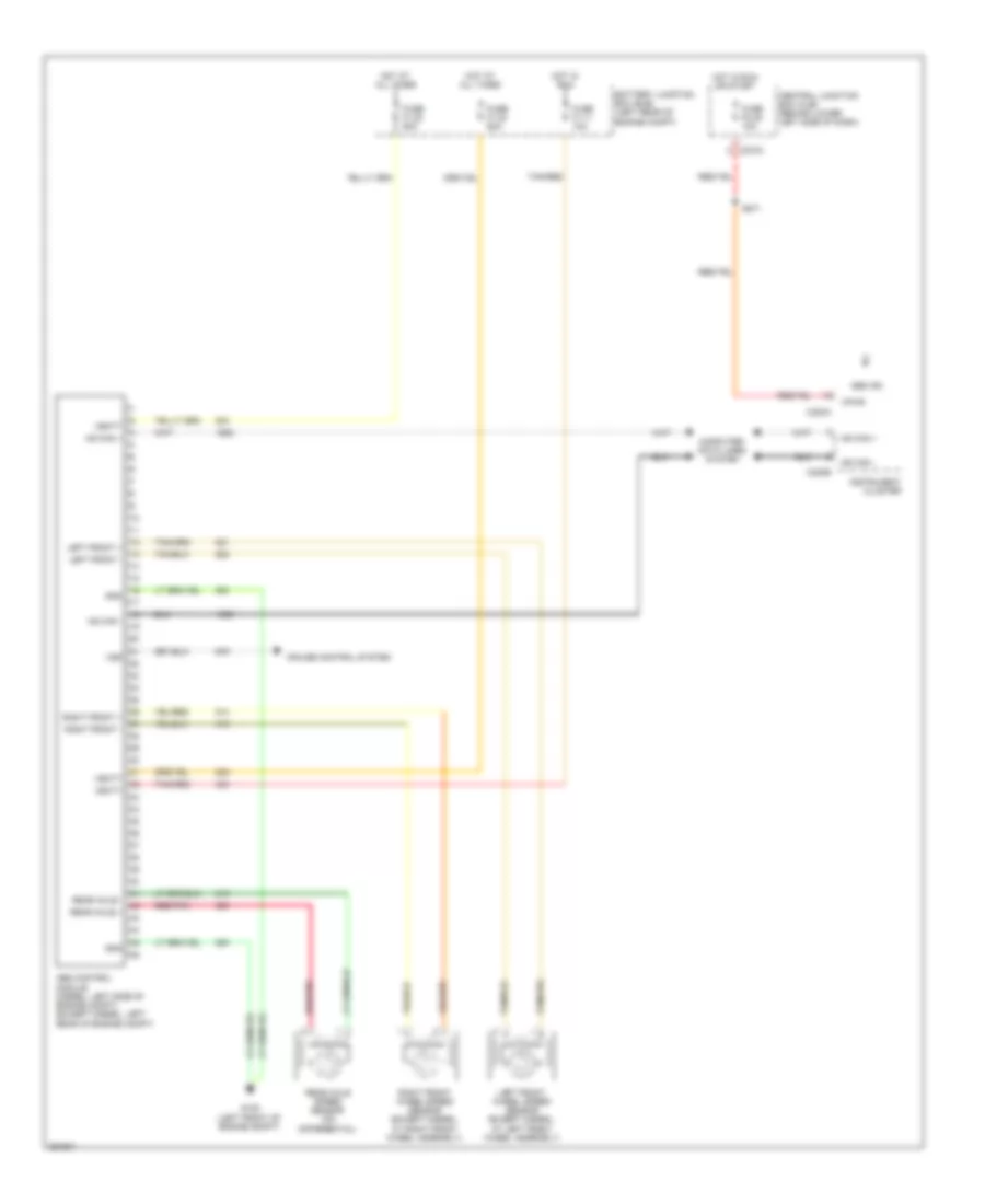
List of elements for Anti-lock Brakes Wiring Diagram for Ford Cab & Chassis F350 Super Duty 2007:
- Abs control module (diesel: left side of engine compt) (except diesel: left rear of engine compt)
- Abs ind
- Battery junction box (bjb) (left rear of engine compt)
- C220a
- C220b
- C270a
- Central junction box (cjb) (behind lower left side of dash)
- Computer data lines system
- Cruise control system
- Fuse f1.11 10a
- Fuse f1.22 60a
- Fuse f1.23 60a
- Fuse f2.45 10a
- G105 (left front of engine compt)
- Gnd
- Hot at all times
- Hot in run
- Hot in run or start
- Hs can +
- Hs can -
- Instrument cluster
- Left front +
- Left front -
- Left front wheel speed sensor (except diesel: at left front wheel assembly)
- Rear axle +
- Rear axle -
- Rear axle speed sensor (on differential)
- Red/pnk
- Right front +
- Right front -
- Right front wheel speed sensor (except diesel: at right front wheel assembly)
- S271
- Tan/red
- Vbatt
- Vpwr
- Vss
 English