POWER DISTRIBUTION
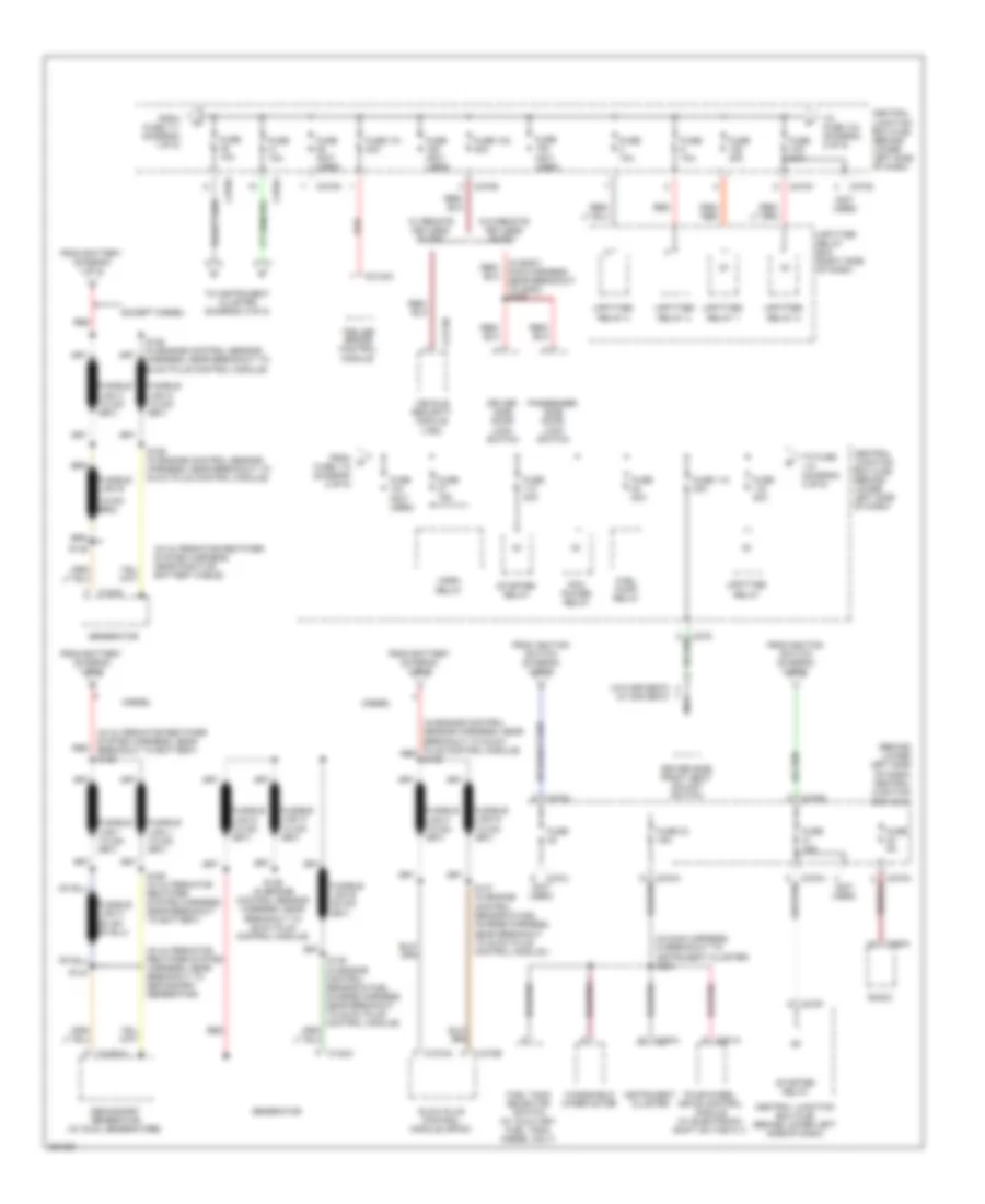
Power Distribution Wiring Diagram (1 of 5) for Ford Cab & Chassis F350 Super Duty 2007

List of elements for Power Distribution Wiring Diagram (1 of 5) for Ford Cab & Chassis F350 Super Duty 2007:
- (behind lower left side of dash) central junction box (cjb)
- (in main harness, in breakout to central junction box) s249
- (in main harness, near breakout for data link connector) s242
- (in main harness, near breakout to brake pedal position switch) s214
- (in main harness, near breakout to instrument cluster) (w/ eatc) s208
- (in main harness, near breakout to restraints control module) (w/ electronic shift on the fly) s230
- (not used)
- 2 of 5)
- 30a
- Adjustable pedal switch (w/o memory)
- Auxiliary relay box 1 (behind left center of dash)
- Battery
- Battery ii (diesel)
- Brake pedal position switch
- C197b
- C202a
- C205a
- C2113b
- C2142b
- C220b
- C228b
- C270a
- C270b
- C270d
- C270e
- C270g
- C270h
- C270i
- C270j
- C270k
- C281a
- C290a
- Central junction box (cjb) (behind lower left side of dash)
- Data link connector (dlc)
- Driver side front heated seat relay
- Electronic automatic temperature control (eatc) module
- Exterior rear view mirror switch
- Four-wheel drive control module (w/ electronic shift on the fly)
- From a fuse 10 (diagram 1 of 5)
- From b fuse 16 (diagram 1 of 5)
- Front cigar lighter
- Fuse
- Fuse (not used)
- Fuse 1 15a
- Fuse 11 20a
- Fuse 111 (not used)
- Fuse 12 20a
- Fuse 13 5a
- Fuse 17 15a
- Fuse 18 20a
- Fuse 19 10a
- Fuse 2 10a
- Fuse 20 15a
- Fuse 21 20a
- Fuse 34 10a
- Fuse 4 20a
- Fuse 6
- Fuse 7 30a
- G201 (behind left side of dash)
- Indicator flasher relay
- Instru- ment panel power point
- Instrument cluster
- Main light switch
- Multi- function switch
- Nca
- Passenger side front seat adjust switch
- Pnk
- Radio
- Red
- S1000 (in engine control sensor harness, near battery) red
- S1002 (in engine control sensor harness, near battery)
- S290
- Starter motor
- To fuse (diagram 2 of 5)
- To fuse 1 (diagram 5 of 5)
- To fuse 108 (diagram 1 of 5)
- To fuse 12 (diagram 1 of 5)
- To fusible links (diagram
- To fusible links (diagram 2 of 5)
- Trailer brake control module
- Vehicle security module (vsm)
- W/ power equipment
- W/ remote keyless entry
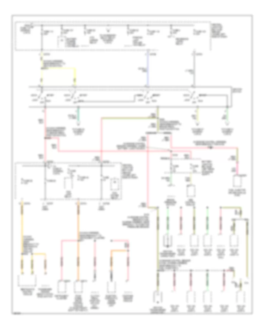
Power Distribution Wiring Diagram (2 of 5) for Ford Cab & Chassis F350 Super Duty 2007
List of elements for Power Distribution Wiring Diagram (2 of 5) for Ford Cab & Chassis F350 Super Duty 2007:
- (behind lower left side of dash) central junction box (cjb)
- (in alternator rectifier system harness, near breakout to battery) s165
- (in alternator rectifier system harness, near breakout to secondary generator)
- (in alternator rectifier system harness, near positive battery cable)
- (in body main harness, near breakout to g300) s289
- (in engine control sensor harness, near breakout to glow plug control module) red s125
- (in main harness, in breakout to instrument cluster) s254
- (not used)
- (w/o sir seat) (w/ sir seat)
- C102a
- C1251a
- C1273a
- C1273b
- C2113b
- C2142a
- C220a
- C270a
- C270b
- C270c
- C270d
- C270e
- C270f
- C270g
- C270h
- C270i
- C270j
- C270k
- C281a
- C290a
- Central junction box (cjb) (behind lower left side of dash)
- Diesel
- Driver side door lock switch
- Driver side front seat adjust switch
- Except diesel
- Four-wheel drive control module (w/ electronic shift on the fly)
- From battery (diagram 1 of 5)
- From d fuse 112 (diagram 2 of 5)
- From fuse 111 (diagram 1 of 5)
- From ignition switch (diagram 3 of 5)
- Fuel pump relay
- Fuel tank selector switch (w/ auxiliary fuel tank, diesel only)
- Fuse
- Fuse (not used)
- Fuse (not used)
- Fuse 101 30a
- Fuse 102 30a
- Fuse 10a
- Fuse 112 30a
- Fuse 15a
- Fuse 20a
- Fuse 30a
- Fuse 33 15a
- Fuse 5a
- Fusible link e
- Fusible link h
- Generator
- Glow plug control module (gpcm)
- Horn relay
- Instrument cluster
- Nca
- Passenger side door lock switch
- Pcm power relay
- Radio
- Red
- S125 (in engine control sensor harness, near breakout to glow plug control module)
- S126 (in engine control sensor harness, near breakout to glow plug control module)
- S144
- S147 (in engine control sensor & fuel charge harness, near breakout to glow plug control module )
- S149
- S149 (in engine control sensor & fuel charge harness, near breakout to glow plug control module)
- S166 (in alternator rectifier system harness, near breakout to battery)
- Secondary generator (w/ dual generators)
- Starter relay
- To fuse (diagram 3 of 5)
- To fuse 104 (diagram 2 of 5)
- To instrument cluster (diagram 4 of 5)
- Trailer brake control module
- Upfitter relay
- Upfitter relay 1
- Upfitter relay 2
- Upfitter relay 3
- Upfitter relay 4
- Upfitter relay box (right side of dash)
- Vehicle security module (vsm)
- W/ remote keyless entry
- W/o remote keyless entry
- Windshield wiper motor
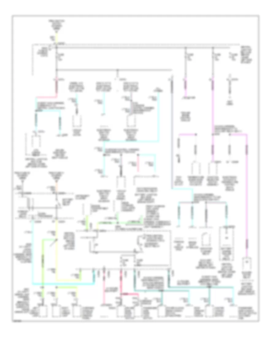
Power Distribution Wiring Diagram (3 of 5) for Ford Cab & Chassis F350 Super Duty 2007
List of elements for Power Distribution Wiring Diagram (3 of 5) for Ford Cab & Chassis F350 Super Duty 2007:
- (in engine control harness, near breakout for g100) s182
- (in engine control sensor & fuel charge harness, near breakout to fuel injector 3) s135
- (in engine control sensor harness, under battery junction box)
- (in main harness, near breakout to brake pedal position switch) s260
- (in main harness, near breakout to ignition switch) s210
- (in main harness, near breakout to instrument cluster) s271
- (in main harness, near breakout to restraints control module) s202
- (not used)
- 5.4l
- 6.8l
- Abs control module
- Acc
- Battery charge trailer tow relay
- Battery junction box (bjb) (left rear of engine compt)
- Brake pressure switch
- C1388c
- C220a
- C270a
- C270b
- C270c
- C270e
- C270f
- C281a
- Central junction box (cjb) (behind lower left side of dash)
- Clutch pedal position switch (m/t, diesel)
- Coil on plug (cop) 1
- Coil on plug (cop) 10
- Coil on plug (cop) 2
- Coil on plug (cop) 3
- Coil on plug (cop) 4
- Coil on plug (cop) 5
- Coil on plug (cop) 6
- Coil on plug (cop) 7
- Coil on plug (cop) 8
- Coil on plug (cop) 9 (6.8l)
- Compass sensor module
- Diesel
- Electro- chromatic inside mirror unit
- Fog lamp relay
- Four wheel drive control module (w/ electronic shift on the fly)
- From e fuse 115 (diagram 2 of 5)
- Fuel injector driver module (ficm)
- Fuse
- Fuse 103 30a
- Fuse 107 20a
- Fuse 10a
- Fuse 110 30a
- Fuse 116 30a
- Fuse 25
- Fuse 26 10a
- Fuse 2a
- Fuse 38 20a
- Fuse 39 15a
- Fuse 45 10a
- Fuse 8 20a
- Gasoline
- Htd mirror relay
- Ignition switch
- Ignition transformer capacitor 1
- Ignition transformer capacitor 2
- Instrument cluster
- Lock
- Nca
- Off
- Parking lamp trailer tow relay
- Passenger air bag deactivation (pad) switch
- Pcm power relay
- Red/
- Restraints control module
- Reversing lamps relay
- Run
- S108
- S130 (in engine control sensor & fuel charge harness, near breakout to injector pressure sensor)
- S258 (in main harness, near breakout to brake pedal position switch)
- Start
- Tan/ red
- To accessory delay relay (diagram 4 of 5)
- To fuse 27 (diagram 4 of 5)
- To fuse 31 (diagram 2 of 5)
- To fuse 48 (diagram 2 of 5)
Power Distribution Wiring Diagram (4 of 5) for Ford Cab & Chassis F350 Super Duty 2007
List of elements for Power Distribution Wiring Diagram (4 of 5) for Ford Cab & Chassis F350 Super Duty 2007:
- (in body main harness, in breakout to central junction box) s209
- (in body main harness, in breakout to front interior/map light assembly)
- (in body main harness, near breakout to g300) (w/o crew cab) s297
- (in engine control harness, near breakout for g100) s124
- (in main harness, near breakout to air bag sliding contact) s206
- (in main harness, near breakout to auxiliary relay box 1)
- (in main harness, near breakout to sunload sensor) (w/ power sliding rear window) s219
- (not used)
- Accessory delay relay
- All others
- Auxiliary relay box 1 (behind left center of dash)
- Battery charge trailer tow relay
- Battery junction box (bjb) (left rear of engine compt)
- Battery saver relay
- Blower motor relay
- Brake shift interlock
- C2142b
- C220a
- C220b
- C228b
- C270a
- C270c
- C270d
- C270f
- C270h
- C270i
- C270j
- C290a
- C294a
- C359
- Central junction box (cjb) (behind lower left side of dash)
- Daytime running lamps (drl) relay
- Diesel w/o electronic shift on the fly or drl
- Driver side door lock switch
- Driver side front heated seat module
- Electronic automatic temperature control (eatc) module
- Electronic shift on the fly (esof) solenoid
- Engine compartment lamp
- From central junction box (diagram 3 of 5)
- From fuse 35 (diagram 2 of 5)
- From fuse 41 (diagram 3 of 5)
- From ignition switch (diagram 3 of 5)
- From j fuse 25 (diagram 3 of 5)
- Front interior/ map lamps assembly (w/ crew & super cab)
- Function selector switch assembly
- Fuse 10a
- Fuse 15a
- Fuse 30a
- Gas w/ a/t & electronic shift on the fly w/o drl
- Gas w/ m/t & electronic shift on the fly w/o drl
- Htd mirror relay
- Indicator flasher relay
- Instrument cluster
- Interior lamps relay
- Left vanity mirror lamp
- Master window adjust switch
- Micro- processor
- Nca
- Overhead console (w/ roof opening panel)
- Parking aid module (pam)
- Passenger side door lock switch
- Passenger side window adjust switch (w/o crew cab)
- Pnk
- Power sliding rear window switch (if equipped)
- Radio
- Rear interior/ map lamps assembly
- Right vanity mirror lamp
- Roof opening panel module
- S229 (w/ vanity lamps) (in main harness, near breakout to instrument cluster)
- S235
- S320
- S906 (w/ crew & super cab)
- S937 (in vanity mirror lamp harness, near breakout to electro -chromatic inside mirror unit)
- Temperature blend door actuator (w/o eatc)
- Tow/ haul switch (w/ a/t)
- Trailer brake control module
- Vacuum pump motor
- Vacuum pump motor (diesel)
- W/ overhead console
- W/ power equipment
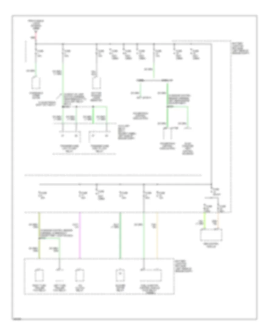
Power Distribution Wiring Diagram (5 of 5) for Ford Cab & Chassis F350 Super Duty 2007
List of elements for Power Distribution Wiring Diagram (5 of 5) for Ford Cab & Chassis F350 Super Duty 2007:
- (diesel)
- (in back up lamp switch harness, near breakout to auxiliary relay box 3) s163
- (in engine control sensor harness, in breakout for battery junction box) s103
- (in engine control sensor harness, left rear engine compartment)
- A/c clutch relay
- Abs control module
- Auxiliary relay box 3 (except diesel: left side of engine compt)
- Battery junction box (bjb) (left rear of engine compt)
- Blower motor relay
- C1381a
- C175b
- Daytime running lamps resistor
- Diesel
- Evap canister vent control solenoid
- From fusible link b (diagram 1 of 5)
- Fuel injector control module (ficm) relay
- Fuse (not used)
- Fuse 10a
- Fuse 15a
- Fuse 20a
- Fuse 30a
- Fuse 40a
- Fuse 50a
- Fuse 60a
- Fuse shunt
- Gasoline
- Left turn trailer tow relay
- Powertrain control module (pcm)
- Red
- Right turn trailer tow relay
- S164
- Transfer case high to low relay
- Transfer case low to high relay
- W/ electronic shift on the fly
- Windshield wiper motor