AIR CONDITIONING
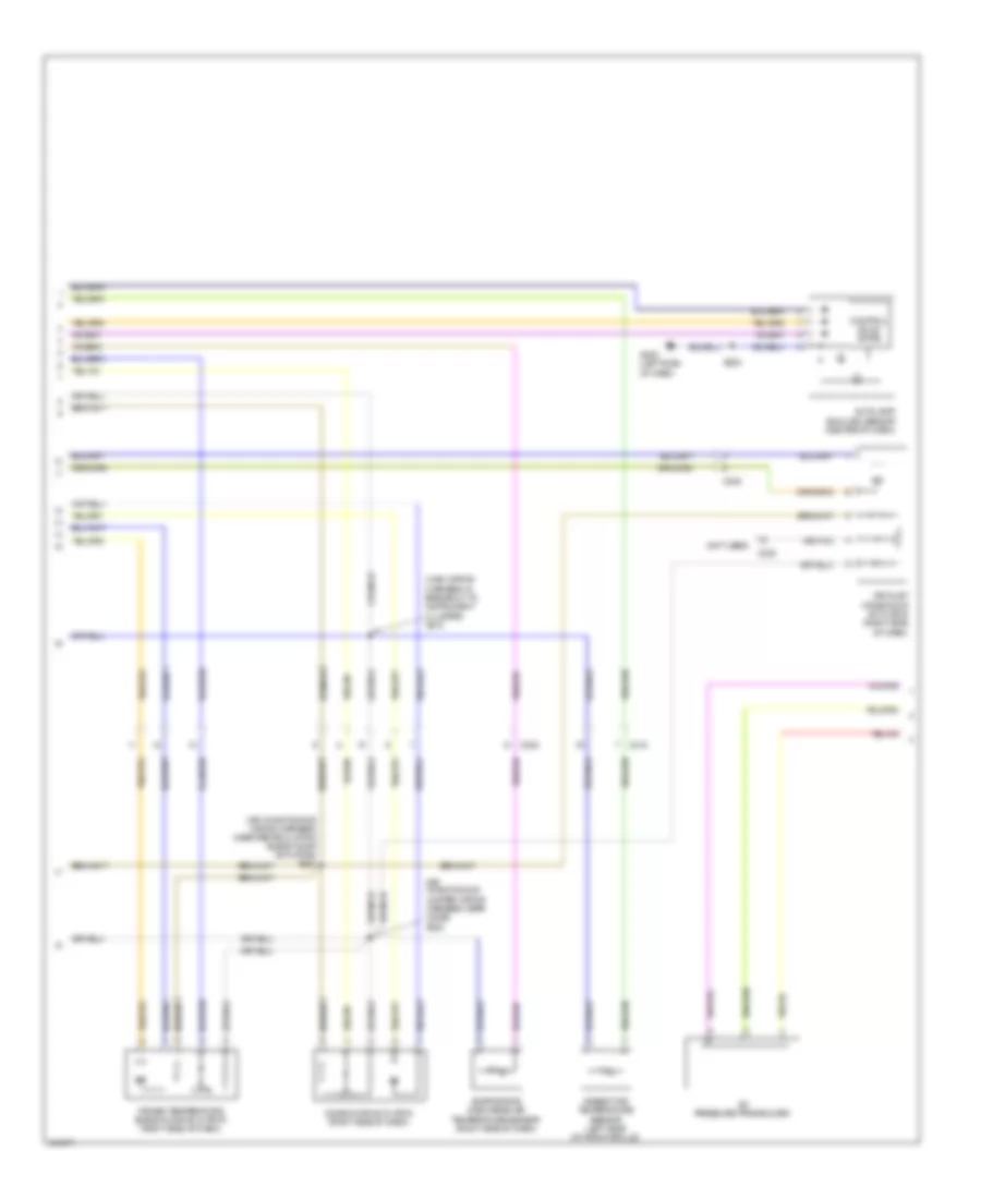
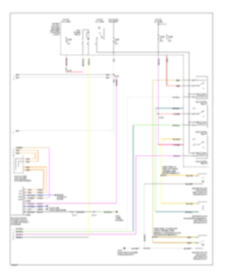
Automatic A/C Wiring Diagram, Except Hybrid (1 of 3) for Ford Escape Limited 2012

List of elements for Automatic A/C Wiring Diagram, Except Hybrid (1 of 3) for Ford Escape Limited 2012:
- (air conditioning jumper wiring harness, near breakout to blower motor)
- 5v vref return
- 5v vref-all act & pots
- Air inlet ccw osa
- Air inlet cw rec
- Ambient temp sens
- Battery junction box (bjb) (left front of engine compt)
- Blower motor
- Blower motor relay
- Blower motor speed control
- C211
- C212
- C2280a
- C2280b
- C2280e
- C2356a
- C2356b
- C237
- C238
- Cbp37
- Ch122
- Ch123
- Ch207
- Ch208
- Ch212
- Ch213
- Ch228
- Ch229
- Ch238
- Ch239
- Chs29
- Chs30
- Computer data lines system
- Defogger
- Drv htd seat rly
- Drv sunload sens
- Drv temp act fdbk
- Drv temp dr ccw (cool)
- Drv temp dr cw (hot)
- Evap temp sens
- Fr blwr relay
- Fuse 10a
- Fuse 40a
- Fuse 5a
- G200 (right side of dash)
- G202 (left side of dash)
- Gd114
- Gnd
- Hot at all times
- Hot in run and start
- Hot in run or acc
- Hvac module-datc
- In car temp sens
- In-vehicle temperature sensor (left side of dash)
- Lh111
- Logic
- Mode 1 act fdbk
- Mode dr 1 ccw def
- Mode dr 1 cw vent
- Mot+
- Mot-
- Mscan+
- Mscan-
- Pass htd seat rly
- Pass sunload sens
- Pass temp act fdbk
- Pass temp dr ccw (hot)
- Pass temp dr cw (cool)
- Passenger temperature blend door actuator (right side of dash)
- Power distribution system
- Pwm
- Rear def/htd mir rly
- Rh111
- S202
- S225
- Sbp15
- Seats system
- Smart junction box (sjb) (center of dash)
- System
- V batt
- V ign
- Variable blwr ctrl (vbc)
- Vdb06
- Vdb07
- Vh101
- Vh406
- Vh407
- Vh414
- Vh416
- Vh417
- Vh436
- Vh440
- Vh441
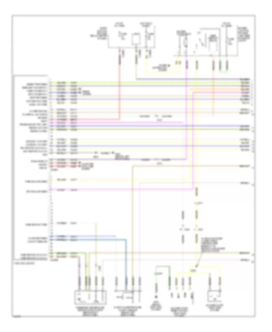
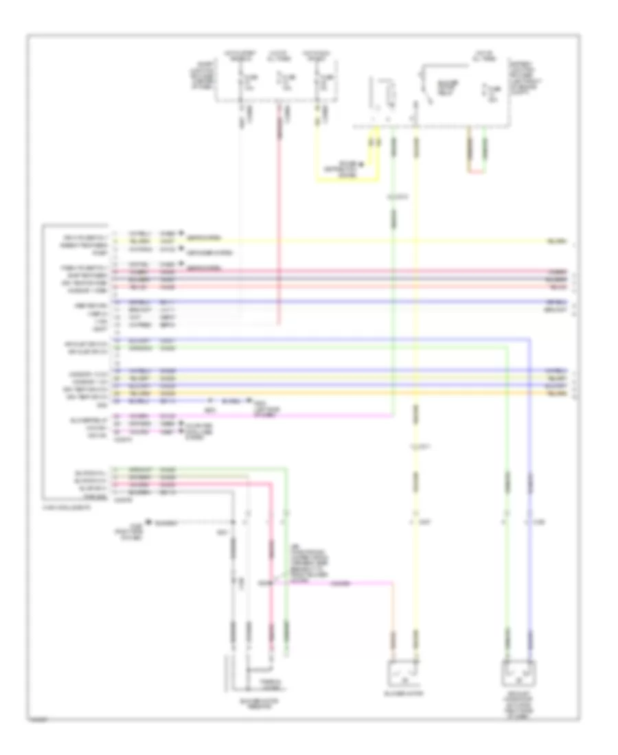
Automatic A/C Wiring Diagram, Except Hybrid (2 of 3) for Ford Escape Limited 2012
List of elements for Automatic A/C Wiring Diagram, Except Hybrid (2 of 3) for Ford Escape Limited 2012:
- (air conditioning jumper wiring harness, near c2029) s222
- (air conditioning wiring harness, near recirculation blend door actuator) s223
- (main wiring harness, in breakout to instrument cluster) s210
- (not used)
- A/c pressure transducer
- Air inlet mode door actuator (right side of dash)
- Ambient air temperature sensor (left side of front grille)
- Autolamp/ sunload sensor (center of dash)
- C212
- C238
- Control solid state
- Driver temperature blend door actuator (right side of dash)
- Evaporator discharge air temperature sensor (right side of dash)
- G202 (left side of dash)
- Mode door actuator (right side of dash)
- S202
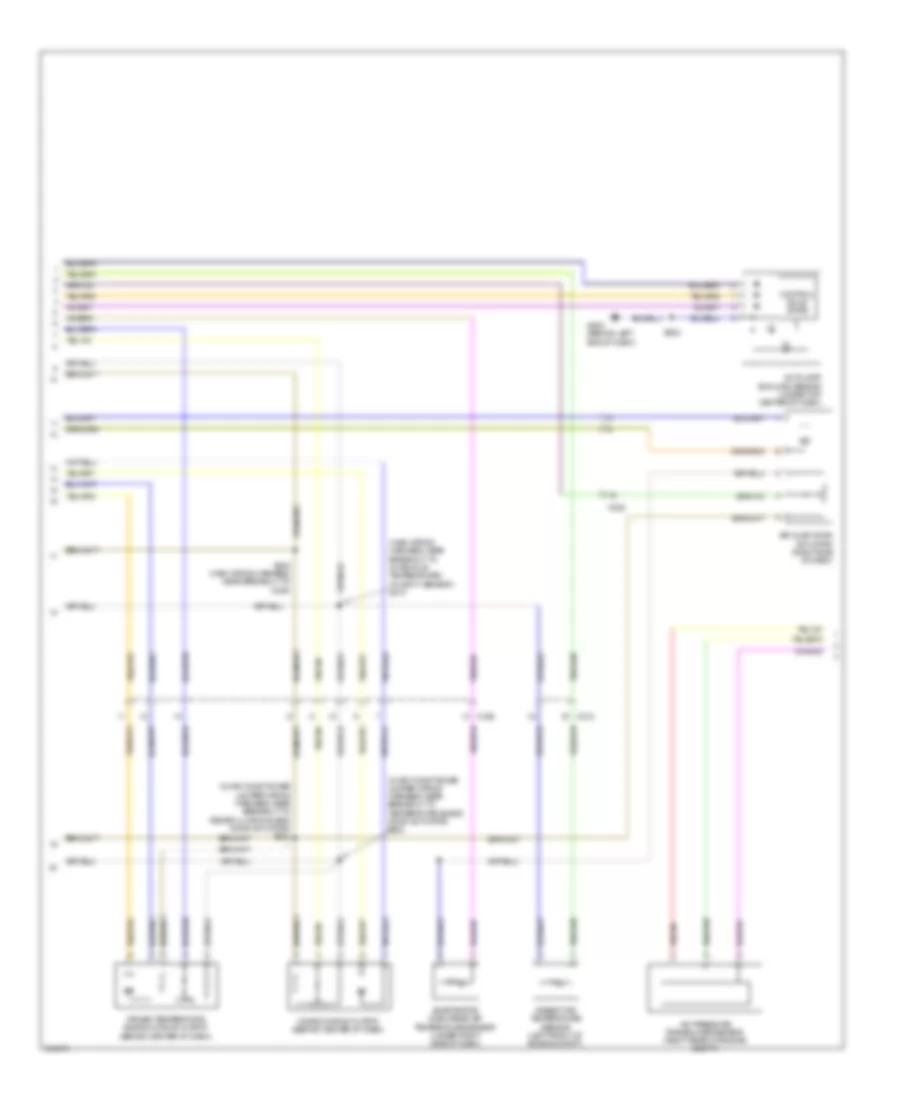
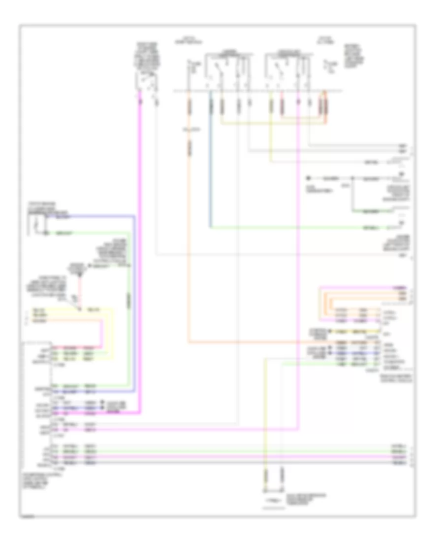
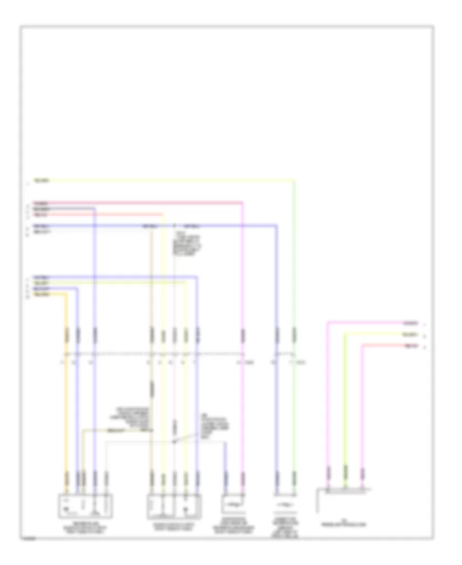
Automatic A/C Wiring Diagram, Except Hybrid (3 of 3) for Ford Escape Limited 2012
List of elements for Automatic A/C Wiring Diagram, Except Hybrid (3 of 3) for Ford Escape Limited 2012:
- (engine control sensor & fuel charge wiring harness, before breakout to fuel injector 3) s118
- (headlamp jumper harness, near breakout to left side turn signal lamp)
- 3.0l
- A/c clutch relay
- A/c compressor clutch field coil (right front of engine compt)
- Accr
- Acpt
- Battery junction box (bjb) (left front of engine compt)
- C175b
- C175e
- Can+
- Can-
- Ce302
- Cec02
- Ceo01
- Ch302
- Cht
- Computer data lines system
- Cooling fan high speed relay
- Cooling fan low speed relay
- Cooling fan relay
- Cylinder head temperature (cht) sensor
- Engine controls system
- Engine cooling fan motor 1 (front of engine compt)
- Engine cooling fan motor 2 (front of engine compt)
- Engine cooling fan resistor (2.5l)
- Fuse 10a
- Fuse 40a
- G102 (right front of engine compt)
- G104 (left front of engine comp)
- Hfc
- Hot at all times
- Le424
- Lfc
- Pcm power relay
- Pcmrc
- Powertrain control module (pcm) (center rear of firewall)
- Re405
- Re407
- Red
- S100
- S102
- S128
- S140
- Sig rtn
- Sigrtne
- Vdb04
- Vdb05
- Ve712
- Vh433
- Vref
Automatic A/C Wiring Diagram, Hybrid (1 of 4) for Ford Escape Limited 2012
List of elements for Automatic A/C Wiring Diagram, Hybrid (1 of 4) for Ford Escape Limited 2012:
- (in air conditioner jumper wiring harness, near breakout to recirculation blend door actuator)
- 5v vref return
- 5v vref-all act & pots
- Ambient temp sens
- Battery junction box (bjb) (left rear of engine compt)
- Blower motor (right side of dash)
- Blower motor relay
- Blower motor speed control (right side of dash)
- C211
- C212
- C2280a
- C2280b
- C2280e
- C2356a
- C2356b
- C237
- C238
- Ch122
- Ch123
- Ch207
- Ch208
- Ch212
- Ch213
- Ch228
- Ch229
- Ch238
- Ch239
- Chs29
- Chs30
- Computer data lines system
- Drv htd seat rly
- Drv sunload sens
- Drv temp act fdbk
- Drv temp dr ccw (cool)
- Drv temp dr cw (hot)
- Evap temp sens
- Fr blwr relay
- Fuse 10a
- Fuse 40a
- Fuse 5a
- G200 (behind right end of dash)
- G202 (behind left end of dash)
- Gd114
- Gnd
- Hot at all times
- Hot in run or acc
- Humidity sens sig
- Hvac module-datc
- In car temp sens
- In-vehicle temperature/ humidity sensor (behind left side of dash)
- Lh111
- Logic
- Mode 1 act fdbk
- Mode dr 1 ccw def
- Mode dr 1 cw vent
- Mot+
- Mot-
- Mscan+
- Mscan-
- Pass htd seat rly
- Pass sunload sens
- Pass temp act fdbk
- Pass temp dr ccw (hot)
- Pass temp dr cw (cool)
- Passenger temperature blend door actuator (behind right side of dash)
- Power distribution system
- Pwm
- Rear def htd mirr rly
- Rear defrost relay
- Recirc ccw osa
- Recirc cw rec
- Rh111
- Rr defr
- S202
- S225
- Sbp15
- Seats system
- Smart junction box (sjb) (below center of dash)
- V batt
- Variable blwr ctrl (vbc)
- Vdb06
- Vdb07
- Vh101
- Vh406
- Vh407
- Vh413
- Vh414
- Vh416
- Vh417
- Vh436
- Vh438
- Vh440
- Vh441
Automatic A/C Wiring Diagram, Hybrid (2 of 4) for Ford Escape Limited 2012
List of elements for Automatic A/C Wiring Diagram, Hybrid (2 of 4) for Ford Escape Limited 2012:
- (in air conditioner jumper wiring harness, near breakout to recirculation blend door actuator) s223
- (in air conditioner jumper wiring harness, near breakout to temperature blend door actuator) s222
- (main wiring harness, near breakout to in-vehicle temperature/ humidity sensor) s210
- A/c pressure transducer sensor (right rear of engine compt)
- Air inlet door actuator (right side of dash)
- Ambient air temperature sensor (left front of engine compt)
- Autolamp/ sunload sensor (under top center of dash)
- C212
- C238
- Control solid state
- Driver temperature blend door actuator (behind center of dash)
- Evaporator discharge air temperature sensor (under right side of dash)
- G202 (behind left end of dash)
- Mode door actuator (behind center of dash)
- S202
- S242 (main wiring harness, near breakout to c238)
Automatic A/C Wiring Diagram, Hybrid (3 of 4) for Ford Escape Limited 2012
List of elements for Automatic A/C Wiring Diagram, Hybrid (3 of 4) for Ford Escape Limited 2012:
- (dash panel to headlamp junction wiring harness, near breakout to battery
- (power pack engine wiring harness, near breakout to powertrain control module) s104
- (right side of engine compt, near strut tower) 1) above 29psi 2) below 25psi a/c cycling switch
- (top of engine)
- Aclpcs
- Acpt
- Auxiliary evaporator discharge air thermistor
- Battery junction box (bjb) (left rear of engine compt)
- C175b
- C175e
- C175t
- C210
- C4227a
- C4227b
- Cbb25
- Ce302
- Ce318
- Cec01
- Cec02
- Cec11
- Ch307
- Ch422
- Cht
- Computer data lines system
- Cybo3
- Cybo4
- Cylinder-head temperature sensor
- Engine controls system
- Fuse 10a
- Fuse 5a
- G105 (near battery)
- Heater pump motor (left front of engine compt)
- Heater pump relay
- Hfc
- Hot at all times
- Hot in start and run
- Hpcr
- Hs can +
- Hs can -
- Hs can+
- Hs can-
- Hvtmu+
- Hvtmu-
- Hyto3
- Hyto4
- Int+
- Int-
- Junction box (bjb))
- Le424
- Lfc
- M/e coolant pump motor (front of engine compt)
- M/e coolant pump relay
- Mecp
- Mfc
- Pcmrc
- Powertrain control module (pcm) (rear center of firewall)
- Re405
- Re407
- Ryb07
- S111
- S124
- Sig rtn-c
- Sigrtne
- Starting/ charging system
- Traction battery control module
- Txv emp rtn
- Txv temp
- Vdb04
- Vdb05
- Ve712
- Vh433
- Vpwr
- Vref-c
- Vyb07
Automatic A/C Wiring Diagram, Hybrid (4 of 4) for Ford Escape Limited 2012
List of elements for Automatic A/C Wiring Diagram, Hybrid (4 of 4) for Ford Escape Limited 2012:
- (dash panel to headlamp wiring harness, near battery breakout) s130
- (dash panel to headlamp wiring harness, near breakout to engine cooling fan dropping resistor 1) s131
- Air conditioning control module (lower left front of engine)
- Battery junction box (bjb) (left rear of engine compt)
- C113
- C1469a
- C1469b
- Ch401
- Computer data lines system
- Cybo4
- Cybo5
- Engine controls system
- Engine cooling fan dropping resistor 1 (left front of engine compt)
- Engine cooling fan motor 1 (left front of engine compt)
- Engine cooling fan motor 2 (right front of engine compt)
- Fan control relay 1
- Fan control relay 2
- Fan control relay 3
- Fuse 10a
- Fuse 40a
- G102 (right front corner of engine compt)
- G104 (near battery)
- Gd123
- High voltage junction box (non-serviceable)
- Hot at all times
- Hot in run and start
- Hv+
- Hv-
- Hvin
- Hvip
- Hybo3
- Hybo4
- Pcm power relay
- Red
- S113
- S116
- S125
- S134
- S146
- Vdbo4
- Vdbo5
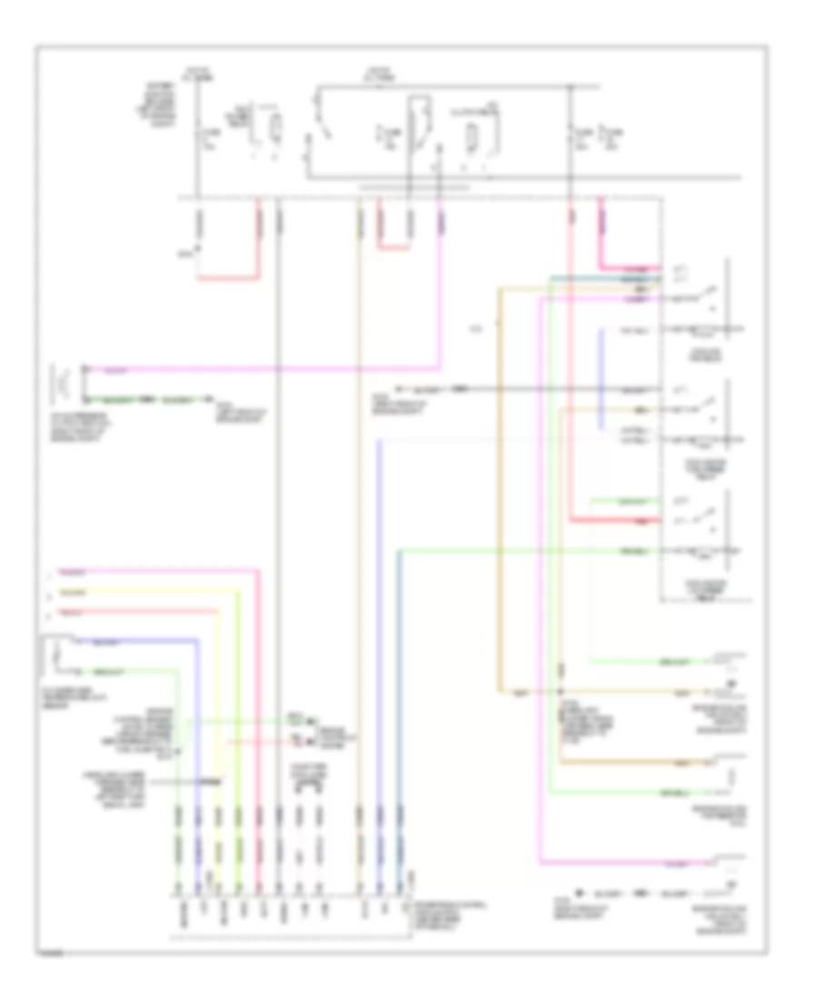
Manual A/C Wiring Diagram (1 of 3) for Ford Escape Limited 2012
List of elements for Manual A/C Wiring Diagram (1 of 3) for Ford Escape Limited 2012:
- (air conditioning jumper wiring harness, near breakout to front blower motor)
- Air inlet dr ccw
- Air inlet dr cw
- Air inlet mode door actuator (right side of dash)
- Ambient temp sens
- Battery junction box (bjb) (left front of engine compt)
- Blower motor
- Blower motor relay
- Blower motor resistor
- Blower relay
- Blwr sw h
- Blwr sw m-h
- Blwr sw m-l
- C211
- C212
- C2280a
- C2280b
- C2280e
- C2357a
- C2357b
- C237
- C238
- Cbp37
- Ch122
- Ch123
- Ch207
- Ch208
- Ch228
- Ch229
- Ch238
- Ch239
- Ch428
- Ch429
- Ch430
- Chs29
- Chs30
- Computer data lines system
- Defogger system
- Drv htd seat rly
- Drv temp dr ccw
- Drv temp dr cw
- Drv temp dr fdbk
- Evap temp sens
- Fuse 10a
- Fuse 40a
- Fuse 5a
- G200 (right side of dash)
- G202 (left side of dash)
- Gd112
- Gd114
- Gnd
- Hot at all times
- Hot in run or acc
- Hot in start and run
- Hvac module-emtc
- Lh111
- Mode dr 1 ccw
- Mode dr 1 cw
- Mode dr 1 fdbk
- Ms can+
- Ms can-
- Pass htd seat rly
- Power distribution system
- Pwr gnd
- R-def
- Rh111
- S201
- S202
- S224
- Sbp15
- Seats system
- Smart junction box (sjb) (center of dash)
- Thermal limiter
- V batt
- V ign
- V ref 5v
- Vdb06
- Vdb07
- Vh406
- Vh407
- Vh436
- Vh440
- Vref return
Manual A/C Wiring Diagram (2 of 3) for Ford Escape Limited 2012
List of elements for Manual A/C Wiring Diagram (2 of 3) for Ford Escape Limited 2012:
- (air conditioning jumper wiring harness, near c2029) s222
- (air conditioning wiring harness, near recirculation blend door actuator) s223
- A/c pressure transducer
- Ambient air temperature sensor (left side of front grille)
- C212
- C238
- Evaporator discharge air temperature sensor (right side of dash)
- Mode door actuator (right side of dash)
- S210 (main wiring harness, in breakout to instrument cluster)
- Temperature blend door actuator (right side of dash)
Manual A/C Wiring Diagram (3 of 3) for Ford Escape Limited 2012
List of elements for Manual A/C Wiring Diagram (3 of 3) for Ford Escape Limited 2012:
- (engine control sensor & fuel charge wiring harness, before breakout to fuel injector 3) s118
- (headlamp jumper harness, near breakout to left side turn signal lamp)
- 3.0l
- A/c clutch relay
- A/c compressor clutch field coil (right front of engine compt)
- Accr
- Acpt
- Battery junction box (bjb) (left front of engine compt)
- C175b
- C175e
- Can+
- Can-
- Ce302
- Cec02
- Ceo01
- Ch302
- Cht
- Computer data lines system
- Cooling fan high speed relay
- Cooling fan low speed relay
- Cooling fan relay
- Cylinder head temperature (cht) sensor
- Engine controls system
- Engine cooling fan motor 1 (front of engine compt)
- Engine cooling fan motor 2 (front of engine compt)
- Engine cooling fan resistor (2.5l)
- Fuse 10a
- Fuse 40a
- G102 (right front of engine compt)
- G104 (left front of engine comp)
- Hfc
- Hot at all times
- Le424
- Lfc
- Pcm power relay
- Pcmrc
- Powertrain control module (pcm) (center rear of firewall)
- Re405
- Re407
- Red
- S100
- S102
- S128
- S140
- Sig rtn
- Sigrtne
- Vdb04
- Vdb05
- Ve712
- Vh433
- Vref