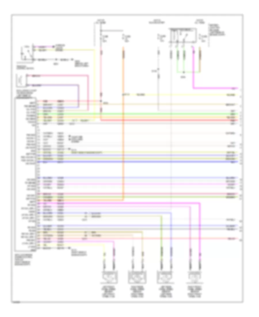
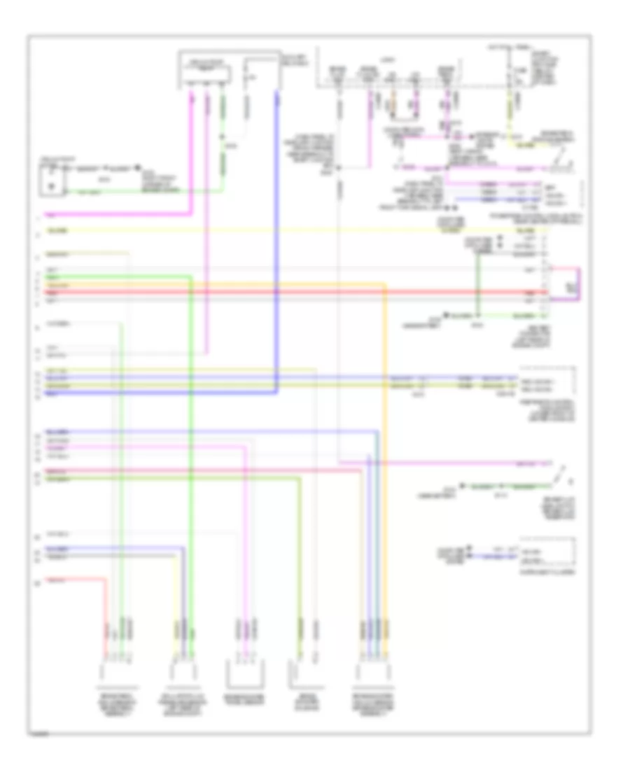
ANTI-LOCK BRAKES
Anti-lock Brakes Wiring Diagram, Except Hybrid for Ford Escape Limited 2012

List of elements for Anti-lock Brakes Wiring Diagram, Except Hybrid for Ford Escape Limited 2012:
- (left front of engine compt) g104
- (left front of engine compt) g105
- (on brake fluid reservoir) brake fluid level switch
- Abs test connector (left side of engine compt)
- Anti-lock brake system (abs) module (left rear of engine compt)
- Battery junction box (bjb) (left front of engine compt)
- Bpp
- Brake fluid rtn sw
- Brake fluid sw
- Brake pedal position switch (left side of dash)
- Brake pedal sw
- C175b
- C2041b
- C210
- C212
- C215
- C2280b
- C2280d
- C2280f
- Cbp34
- Cca15
- Ccb08
- Computer data lines system
- Exterior lights system
- Fuse 15a
- Fuse 20a
- Fuse 50a
- Fuse 5a
- G104 (left front of engine compt)
- G202 (left side of dash)
- Gd120
- Gnd
- Hot at all times
- Hot in start or run
- Hs can +
- Hs can -
- Ign
- Instrument cluster
- Interior lights system
- Left front wheel speed sensor (left front wheel hub)
- Left rear wheel speed sensor (left rear wheel hub)
- Lf gnd
- Lf whl spd +
- Logic
- Lr whl spd +
- Lr whl spd -
- Ms can +
- Ms can -
- Nca
- Powertrain control module (2.5l: center rear of firewall) (3.0l: rear center of firewall)
- Rca17
- Rca18
- Rca19
- Rca20
- Red
- Restraints control module (center of dash)
- Rf gnd
- Rf whl spd +
- Right front wheel speed sensor (right front wheel hub)
- Right rear wheel speed sensor (right rear wheel hub)
- Rr whl spd +
- Rr whl spd -
- Rsc hs can +
- Rsc hs can -
- Rsc hs can h
- Rsc hs can l
- S109
- S111 (headlamp jumper wiring harness, near breakout to left front side lamp)
- S214
- S230 dash panel to headlamp junction wiring harness, near breakout to smart junction box
- S308 (body wiring harness, near key pad switch)
- Sbb09
- Sbb18
- Smart junction box (sjb) (center of dash)
- Tcs sw
- Traction control switch
- Vbatt
- Vca03
- Vca04
- Vca05
- Vca06
- Vca23
- Vca24
- Vdb04
- Vdb05
Anti-lock Brakes Wiring Diagram, Hybrid (1 of 2) for Ford Escape Limited 2012
List of elements for Anti-lock Brakes Wiring Diagram, Hybrid (1 of 2) for Ford Escape Limited 2012:
- Anti-lock brake system control module (right rear of engine compt)
- Battery junction box (bjb) (left rear of engine compt)
- Bst pwm
- Bst pwr
- C210
- C212
- Cb101
- Cbb30
- Cbk03
- Cca15
- Cca22
- Ccb30
- Ccb31
- Ccb32
- Ccb33
- Computer data lines system
- Engine compt)
- Fuse 10a
- Fuse 40a
- Fuse 50a
- G110 (right side of engine compt)
- G112 (right side of
- G202 (behind left end of dash)
- Gd179
- Gnd
- Hot at all times
- Hot in run and start
- Hs can +
- Hs can -
- Ign
- Interior lights system
- Lca16
- Lca27
- Lca37
- Left front wheel speed sensor (left front wheel hub)
- Left rear wheel speed sensor (left rear wheel hub)
- Lf gnd
- Lf whl spd +
- Lr whl spd +
- Lr whl spd -
- Mp gnd
- Mp sig
- Nca
- Pas gnd
- Pas sense
- Pas sig1
- Pas sig2
- Pm sense
- Ps gnd
- Ps sens
- Ps sig
- Rca16
- Rca17
- Rca18
- Rca19
- Rca20
- Rca27
- Rca37
- Rcb33
- Red
- Rf gnd
- Rf whl spd +
- Right front wheel speed sensor (right front wheel hub)
- Right rear wheel speed sensor (right rear wheel hub)
- Rr whl spd +
- Rr whl spd -
- Rsc hs can h
- Rsc hs can l
- S112
- S123
- S146
- S155
- S202
- Sbb09
- Sbb18
- Simulator cut-off valve solenoid (left rear of engine compt)
- Tcs sw
- Traction control switch
- Vac gnd
- Vac pump
- Vac sens
- Vac sig1
- Vac sig2
- Vac43
- Vacrc
- Vacuum pump relay
- Vbatt
- Vca03
- Vca04
- Vca05
- Vca06
- Vca13
- Vca22
- Vca23
- Vca24
- Vca30
- Vca38
- Vca39
- Vcb34
- Vdb04
- Vdb05
- Vol pwm
- Vol pwr
Anti-lock Brakes Wiring Diagram, Hybrid (2 of 2) for Ford Escape Limited 2012
List of elements for Anti-lock Brakes Wiring Diagram, Hybrid (2 of 2) for Ford Escape Limited 2012:
- (dash panel to headlamp junction wiring harness, near breakout to smart junction box)
- Abs test connector (left rear of engine compt)
- Auxiliary relay box
- Bpp
- Brake booster solenoid
- Brake booster travel sensor
- Brake booster vacuum sensor (brake booster assembly)
- Brake fluid level switch (brake fluid reservoir)
- Brake fluid sw
- Brake fluid sw rtn
- Brake pedal angle sensor (brake pedal assembly)
- Brake pedal position switch
- Brake pedal sw
- C175b
- C2041b
- C210
- C215
- C2280b
- C2280d
- C2280f
- Ccb08
- Computer data lines system
- Exterior lights system
- Fuse 15a
- G102 (right front corner of engine compt)
- G104 (near battery)
- G105 (near battery)
- Hot at all times
- Hs can +
- Hs can -
- Instrument cluster
- Logic
- Ms can +
- Ms can -
- Powertrain control module (pcm) (rear center of firewall)
- Red
- Restraints control module (rcm) (under front of center console)
- Rsc hs can +
- Rsc hs can -
- S113
- S124
- S134
- S141 (dash panel to headlamp junction harness, near breakout to left front turn signal lamp)
- S148
- S230
- S308 (body wiring harness, near breakout to c314)
- Simulator fluid pressure sensor (left rear of engine compt)
- Smart junction box (sjb) (below center of dash)
- Vacuum pump motor
- Vacuum pump relay
- Vca23
- Vca24
- Vdb04
- Vdb05