COOLING FAN
Cooling Fan Wiring Diagram, Except Hybrid for Ford Escape Limited 2012

List of elements for Cooling Fan Wiring Diagram, Except Hybrid for Ford Escape Limited 2012:
- (engine control sensor & fuel charge wiring harness, before breakout to fuel injector 3) s118
- 3.0l
- Battery junction box (bjb) (left front of engine compt)
- C175b
- C175e
- Can+
- Can-
- Ce302
- Cec02
- Ceo01
- Cht
- Computer data lines system
- Cooling fan high speed relay
- Cooling fan low speed relay
- Cooling fan relay
- Cylinder head temperature (cht) sensor
- Engine controls system
- Engine cooling fan motor 1 (front of engine compt)
- Engine cooling fan motor 2 (front of engine compt)
- Engine cooling fan resistor (2.5l)
- Fuse 10a
- Fuse 40a
- G102 (right front of engine compt)
- Hfc
- Hot at all times
- Lfc
- Pcm power relay
- Pcmrc
- Powertrain control module (pcm) (3.0l: rear center of firewall) (2.5l: center rear of firewall)
- Re405
- Red
- S102
- S140
- Sigrtne
- Vdb04
- Vdb05
- Ve712
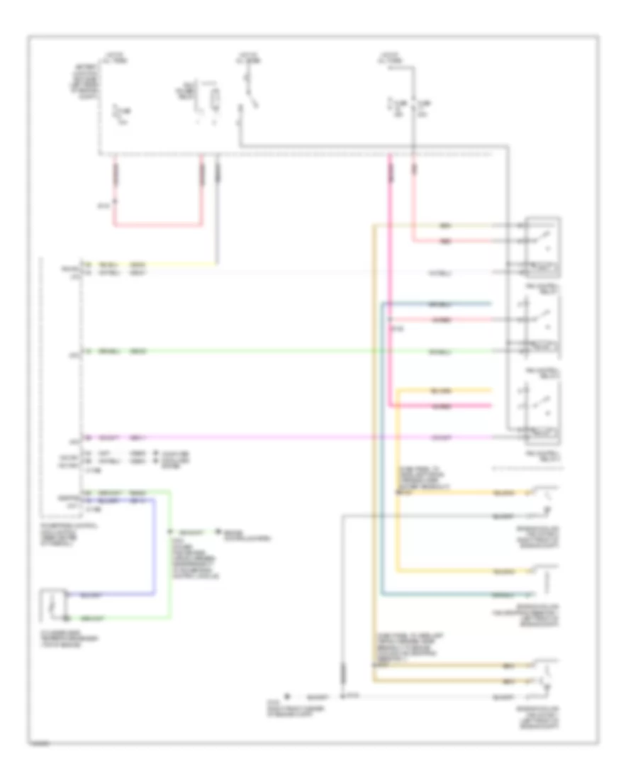
Cooling Fan Wiring Diagram, Hybrid for Ford Escape Limited 2012
List of elements for Cooling Fan Wiring Diagram, Hybrid for Ford Escape Limited 2012:
- hs can-
- (dash panel to headlamp wiring harness, near battery breakout) s130
- (dash panel to headlamp wiring harness, near breakout to engine cooling fan dropping resistor 1) s131
- Battery junction box (bjb) (left rear of engine compt)
- C175b
- C175e
- Ce302
- Cec01
- Cec02
- Cec11
- Cht
- Computer data lines system
- Cylinder-head temperature sensor (top of engine)
- Engine controls system
- Engine cooling fan dropping resistor 1 (left front of engine compt)
- Engine cooling fan motor 1 (left front of engine compt)
- Engine cooling fan motor 2 (right front of engine compt)
- Fan control relay 1
- Fan control relay 2
- Fan control relay 3
- Fuse 10a
- Fuse 40a
- G102 (right front corner of engine compt)
- Hfc
- Hot at all times
- Hs can+
- Lfc
- Mfc
- Pcm power relay
- Pcmrc
- Powertrain control module (pcm) (rear center of firewall)
- Re405
- Red
- S104 (power pack engine wiring harness, near breakout to powertrain control module)
- S116
- S125
- S134
- Sigrtne
- Vdb04
- Vdb05
- Ve712