ENGINE PERFORMANCE
2.5L
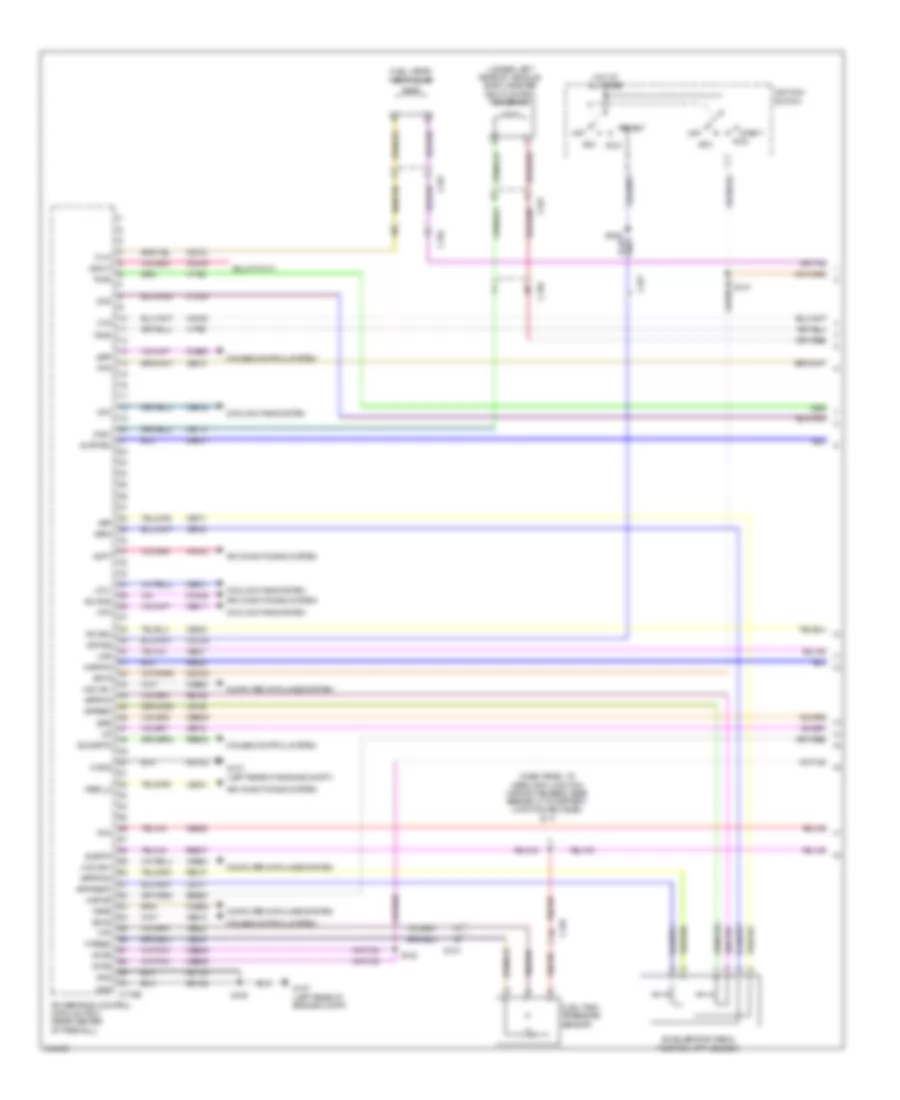
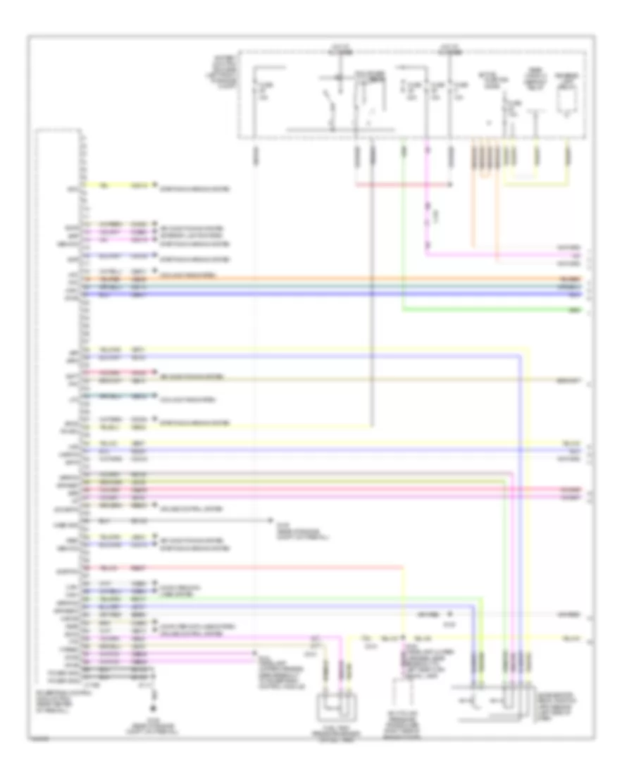
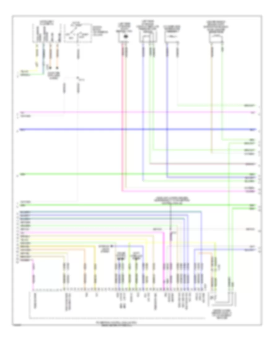
2.5L, Engine Performance Wiring Diagram (1 of 5) for Ford Escape Limited 2012

List of elements for 2.5L, Engine Performance Wiring Diagram (1 of 5) for Ford Escape Limited 2012:
- (m/t)
- 10a
- 15a
- 20a
- A/c cycling pressure transducer (right side of engine compt)
- Accelerator pedal position (app) sensor (left side of dash)
- Accr
- Acpt
- Air conditioning system
- App
- App2
- Apprtn
- Apprtn2
- Appvref
- Appvref2
- Battery junction box (bjb) (left front of engine compt)
- Bpp
- Bps
- C175b
- C210
- Can+
- Can-
- Canv
- Case gnd
- Cbb29
- Cbk01
- Cbk02
- Ccb08
- Cdb08
- Cdc10
- Cdc12
- Cdc15
- Cdc34
- Cdc35
- Cdc54
- Ce114
- Ce226
- Ce302
- Cec01
- Cec02
- Ces09
- Ch302
- Computer data lines system
- Cooling fans system
- Cruise control system
- Exterior lights system
- Feps
- Fpc
- Fpm
- Ftp
- Ftpref
- Fuel tank pressure sensor (in fuel tank)
- Fuse
- G109 (rear of engine compt, on firewall)
- Gd122
- Gencom
- Genmon
- Hfc
- Hot at all times
- Iat
- Isp-r
- Kapwr
- Le136
- Le137
- Le230
- Le424
- Lfc
- Mafrtn
- Mafs
- Pcm power relay
- Pcmrc
- Power gnd
- Powertrain control module (pcm) (center rear of firewall)
- Re136
- Re137
- Re320
- Re407
- Res08
- S114
- S140
- S144 (headlamp jumper harness, near breakout to powertrain control module)
- Sbb05
- Sccs
- Sccsrtn
- Sigrtnc
- Smc
- Smcs
- Smr
- Starting/charging system
- Vdb04
- Vdb05
- Ve518
- Ve701
- Ve702
- Ve740
- Ve807
- Ve922
- Ves10
- Vh433
- Vpwr
- Vpwrtr-pn
- Vref
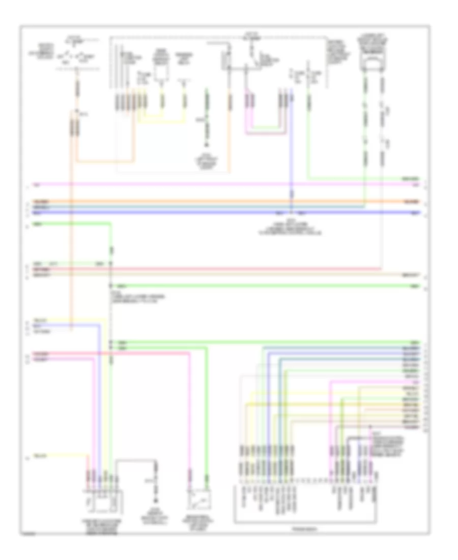
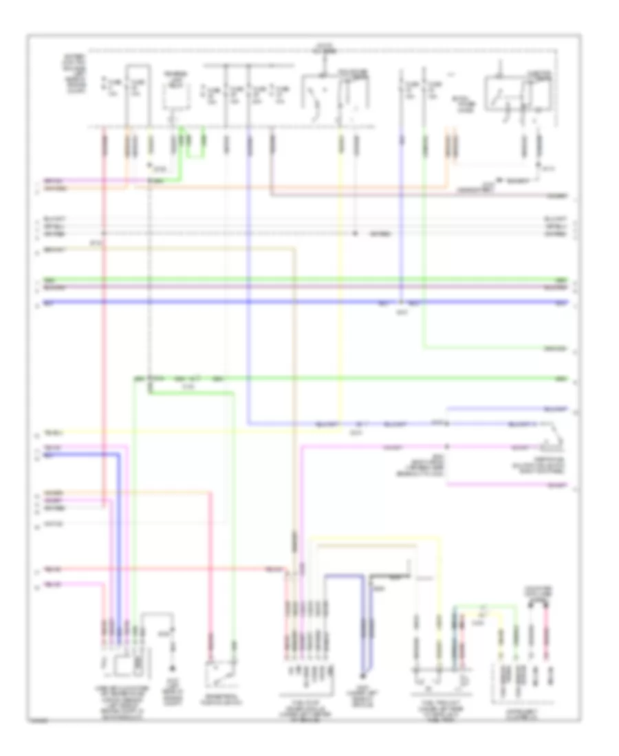
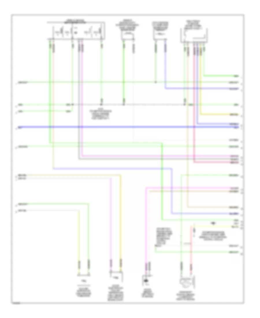
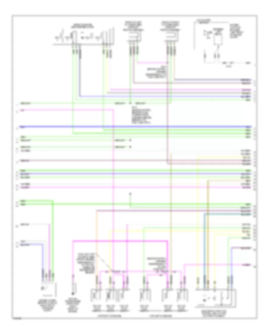
2.5L, Engine Performance Wiring Diagram (2 of 5) for Ford Escape Limited 2012
List of elements for 2.5L, Engine Performance Wiring Diagram (2 of 5) for Ford Escape Limited 2012:
- (m/t)
- (under left side of vehicle) evap canister vent control solenoid
- 15a
- 20a
- Acc
- Battery junction box (bjb) (left front of engine compt)
- Brake pedal position switch (left side of dash)
- C168a
- C168b
- C210
- C327
- Cblr/c456 vfs
- Cet05
- Cet06
- Cet07
- Cet08
- Cet09
- Cet10
- Cet18
- Cet25
- Fuel injector diode
- Fuel injector relay
- Fuse
- Fuse 10a
- G104 (left front of engine compt)
- G109 (rear of engine compt,
- Hot at all times
- Ignition switch (on steering column)
- Le111
- Lpc vfs
- Mass air flow/intake air temperature (maf/iat) sensor (rear of engine)
- Off
- On firewall)
- Oss
- Re406
- Rear window defrost relay
- Ret24
- Reverse lamp relay
- Run
- S109
- S113
- S114
- S142 (headlamp jumper harness, near breakout to c139)
- S143 (headlamp jumper harness, near breakout to powertrain control module)
- S146
- S147 (engine control wiring harness, near breakout to output shaft speed sensor)
- Sol pwr
- Ssa cb1234 vfs
- Ssb c35r vfs
- Ssc cb26 vfs
- Sse on/off sol
- Start
- Tcc vfs
- Tft
- Tft sig rtn
- Transmission
- Trs
- Trs/oss gnd
- Trs/oss pwr
- Tss
- Tss gnd
- Tss pwr
- Vet26
- Vet27
- Vet32
- Vet33
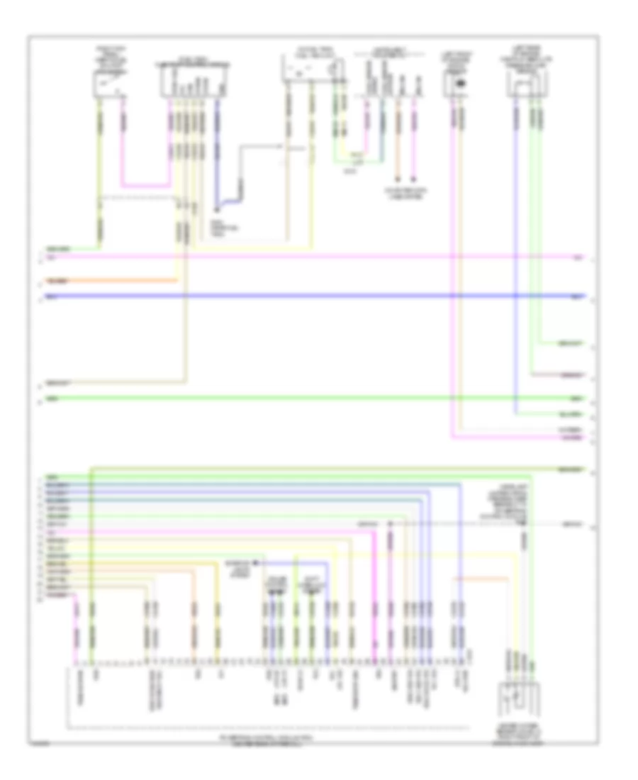
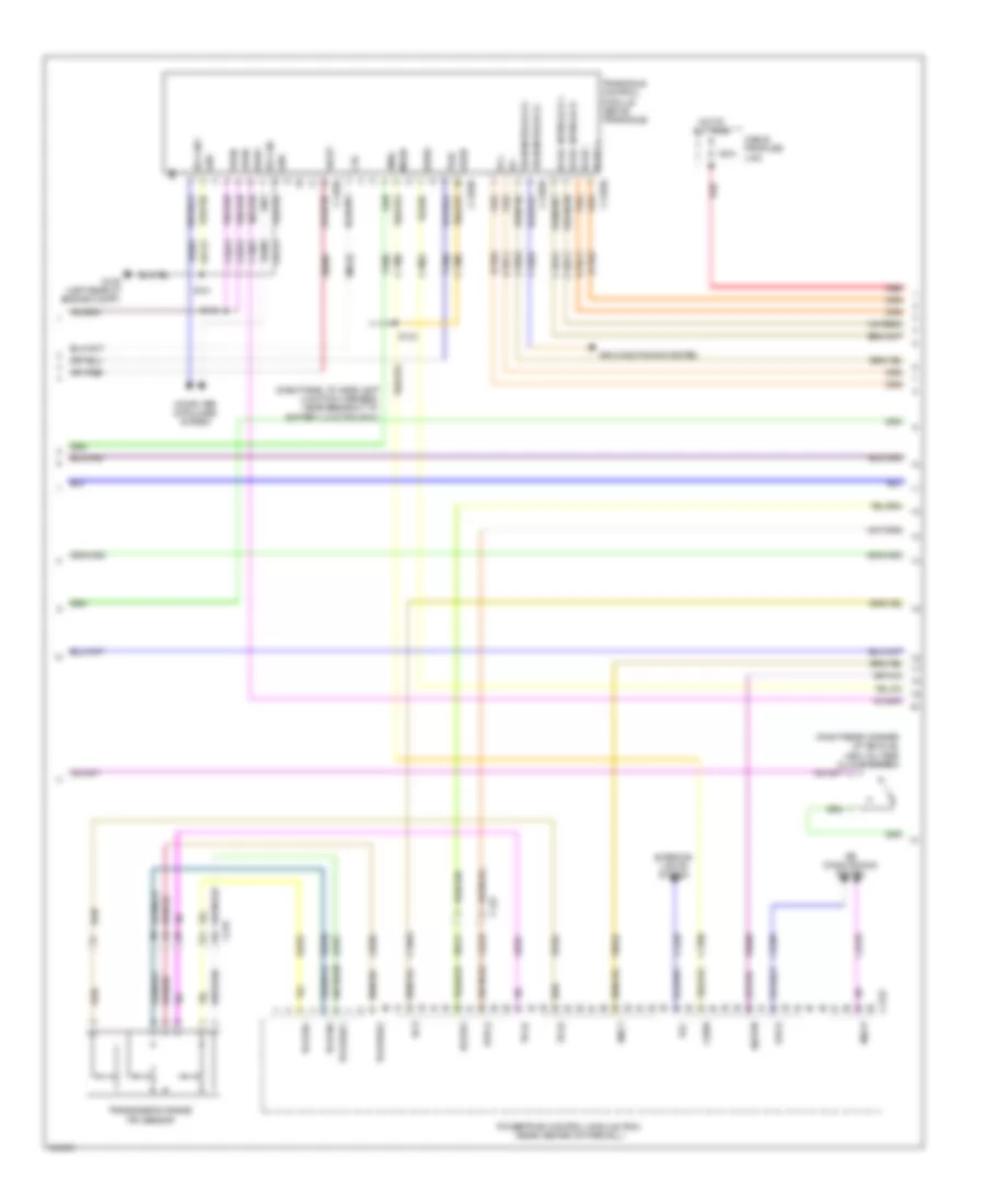
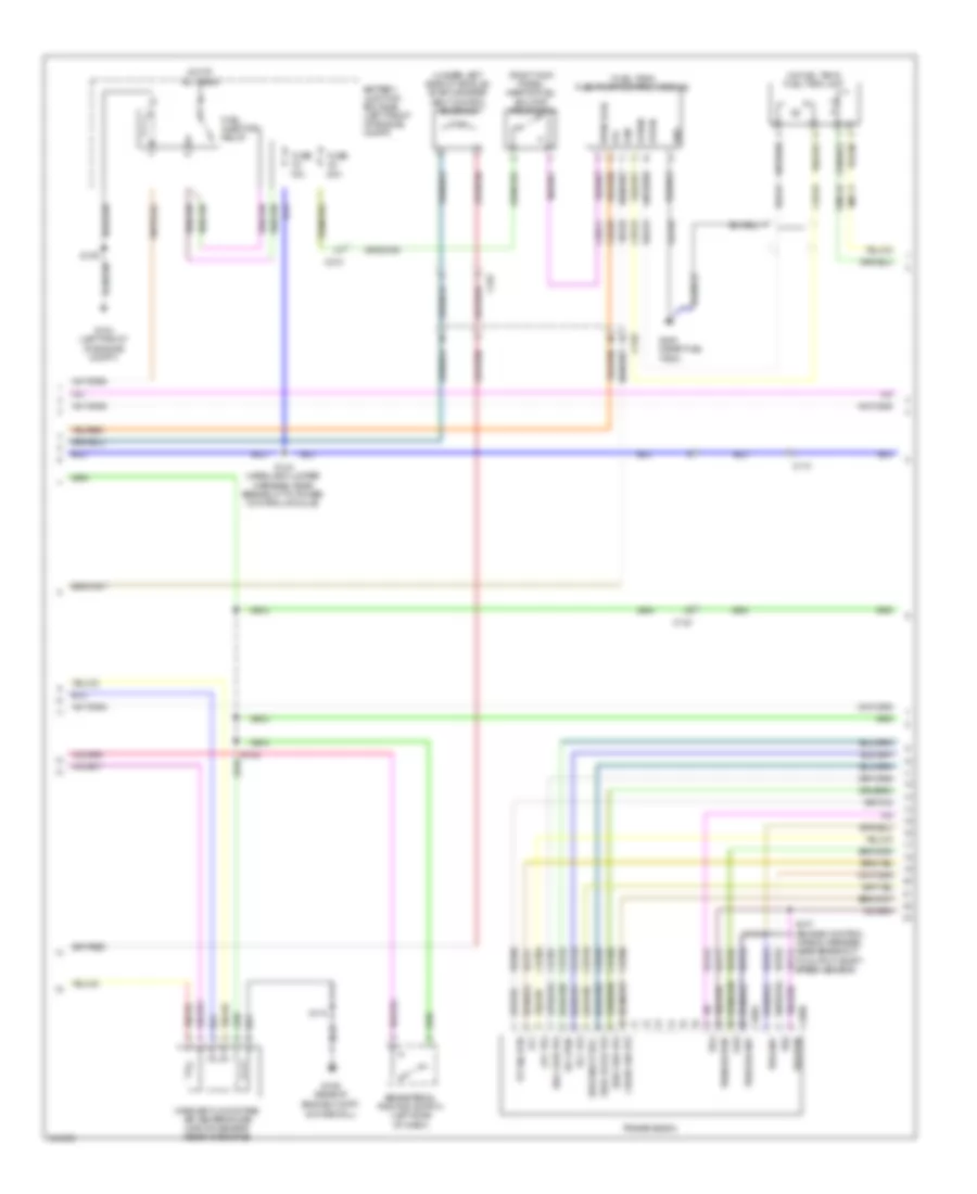
2.5L, Engine Performance Wiring Diagram (3 of 5) for Ford Escape Limited 2012
List of elements for 2.5L, Engine Performance Wiring Diagram (3 of 5) for Ford Escape Limited 2012:
- (fuel tank) fuel pump control module
- (headlamp jumper wiring harness, near breakout to powertrain control module) s121
- (in fuel tank) fuel tank unit
- (left front of engine) knock sensor
- (left rear of engine) manifold absolute pressure (map) sensor
- (m/t)
- (right kick panel) inertia fuel shutoff (ifs) switch
- C175t
- C210
- C215
- Ce226
- Ce233
- Ce515
- Ce903
- Ce911
- Cet05
- Cet06
- Cet07
- Cet08
- Cet09
- Cet10
- Cet18
- Cet21
- Cet25
- Cet34
- Cls28
- Computer data lines system
- Cpp-bt
- Cpp-tt
- Cruise control system
- Exterior lights system
- Fpc
- Fpm
- Fppwr
- Fprtn
- Fuel sender return
- Fuel sender signal
- G400 (near fuel
- Gd159
- Gnd
- Heated oxygen sensor (ho2s) 12 (right front of engine, in exhaust)
- Ho2s-12
- Htr-12
- Instrument cluster (ic)
- Le111
- Lpc vfs
- Ms can+
- Ms can-
- Oss
- Powertrain control module (pcm) (center rear of firewall)
- Re406
- Re515
- Ret24
- Rlc
- Rmc32
- Shift interlock system
- Sigrtnt
- Sol pwr
- Ssa cb1234 vfs
- Ssb c35r vfs
- Ssc cb26 vfs
- Ssd cblr/cb456
- Sse on/off sol
- Tank)
- Tcc vfs
- Tcs
- Tft
- Trs
- Trs/oss vpwr
- Tss
- Tss/oss/tr gnd
- Ve518
- Ve731
- Vet26
- Vet27
- Vet32
- Vet33
- Vmc11
- Vper fuel
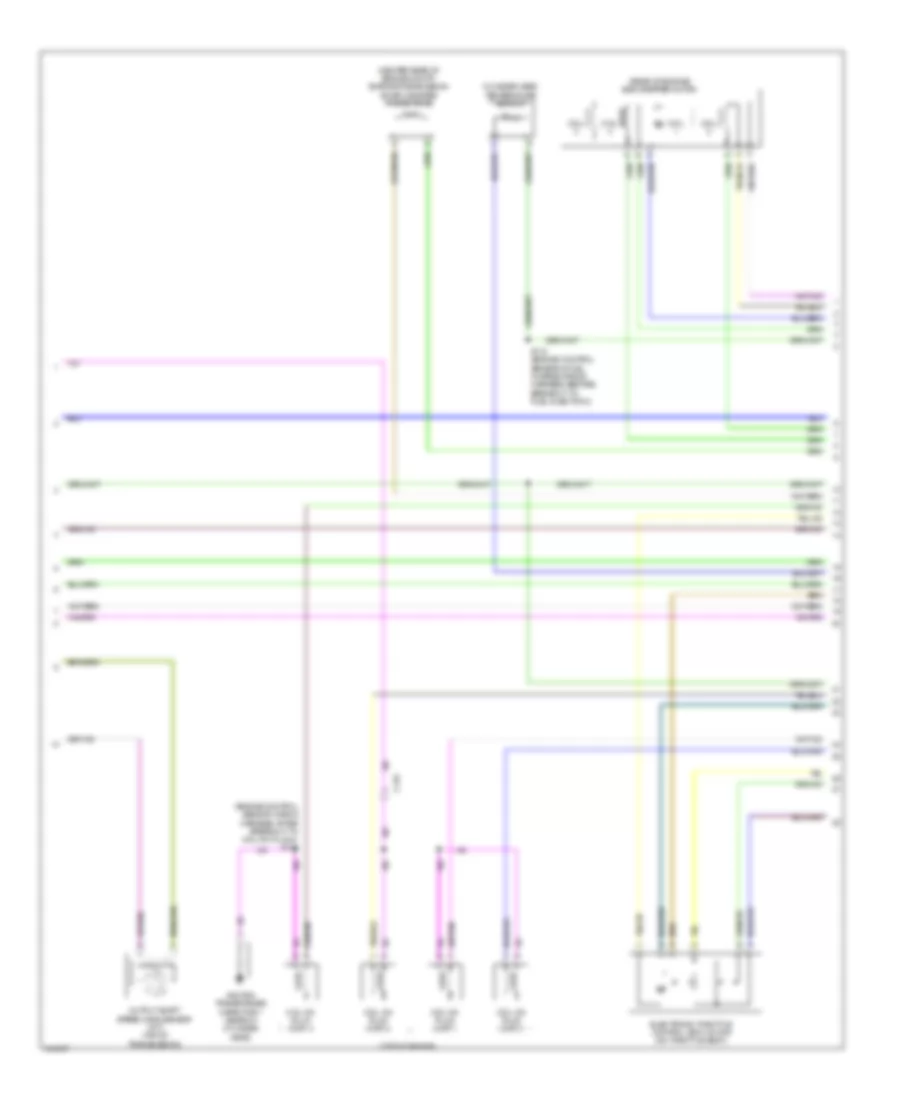
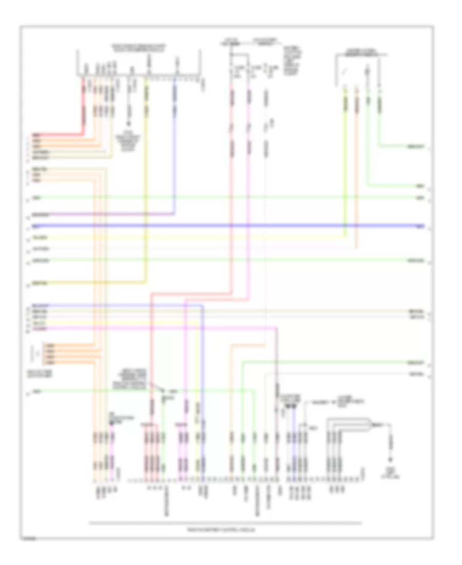
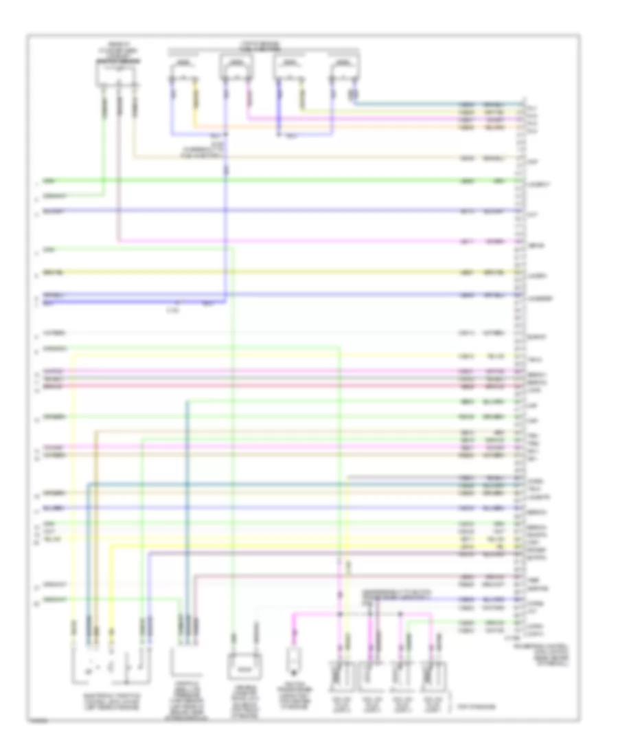
2.5L, Engine Performance Wiring Diagram (4 of 5) for Ford Escape Limited 2012
List of elements for 2.5L, Engine Performance Wiring Diagram (4 of 5) for Ford Escape Limited 2012:
- (center rear of engine compt) evaporative emission (evap) canister purge valve
- (engine control sensor wiring harness, after breakout to coil on plug 4) s135
- (rear of engine) egr stepper motor
- (top of engine)
- C133
- Coil
- Coil on plug (cop) 1
- Coil on plug (cop) 2
- Coil on plug (cop) 3
- Coil on plug (cop) 4
- Cylinder head temperature sensor
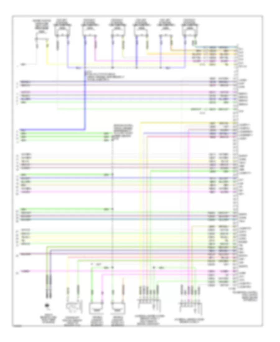
- Electronic throttle control (etc) motor (on throttle body)
- Ignition transformer capacitor 1 (rear of cylinder head)
- Output shaft speed (oss) sensor (m/t) (top of transmission)
- S118 (engine control sensor & fuel charge wiring harness, before breakout to fuel injector 3)
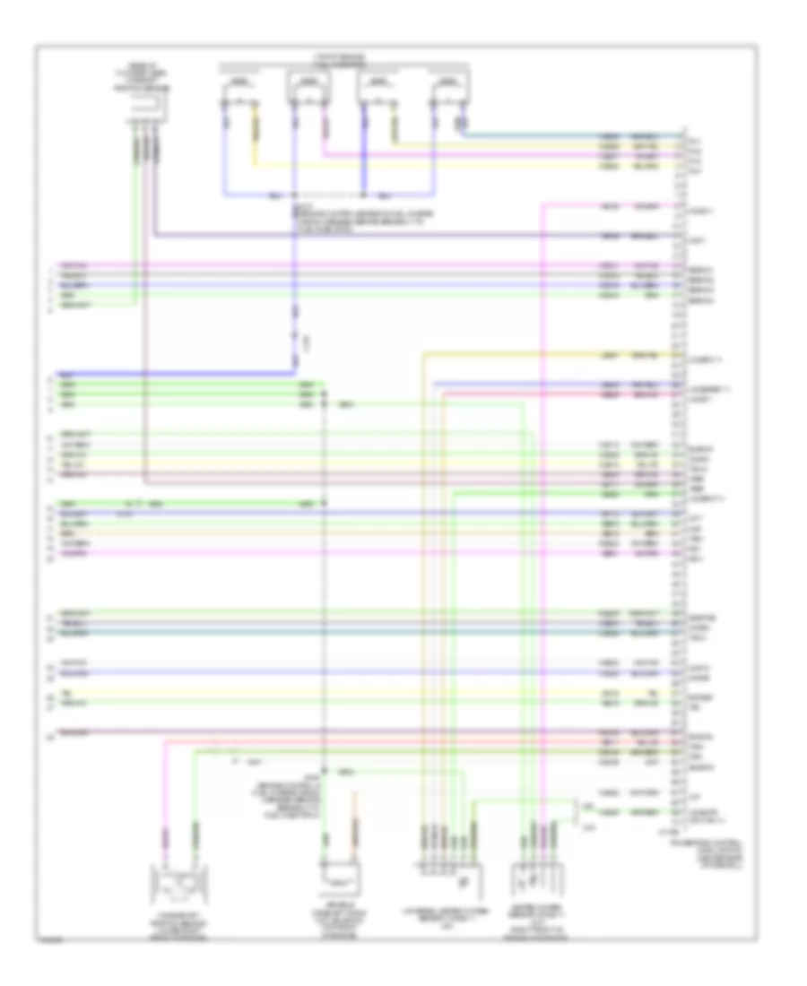
2.5L, Engine Performance Wiring Diagram (5 of 5) for Ford Escape Limited 2012
List of elements for 2.5L, Engine Performance Wiring Diagram (5 of 5) for Ford Escape Limited 2012:
- (a/t)
- (m/t)
- (m/t) (right front of engine, in exhaust)
- (rear of cylinder head) camshaft position sensor
- (top of engine) fuel injectors
- C133
- C175e
- Ce101
- Ce102
- Ce103
- Ce104
- Ce113
- Ce205
- Ce206
- Ce207
- Ce208
- Ce235
- Ce303
- Ce304
- Ce305
- Ce306
- Ce412
- Ce422
- Ce426
- Cht
- Cmp 1
- Cop1a
- Cop2d
- Cop3b
- Cop4c
- Cpk+
- Cpk-
- Crankshaft position sensor (lower right front of engine)
- De135
- Egrmc1
- Egrmc2
- Egrmc3
- Egrmc4
- Etcref
- Etcrtn
- Evapcp
- Heated oxygen sensor (ho2s) 11
- Ho2s-11
- Inj1
- Inj2
- Inj3
- Inj4
- Ks1+
- Ks1-
- Le111
- Le134
- Le423
- Le448
- Le451
- Le452
- Map
- Powertrain control module (pcm) (center rear of firewall)
- Re134
- Re135
- Re323
- Re405
- S136 (engine control & fuel charge wiring harness, before breakout to fuel injector 3)
- Shdrtn
- Sigrtne
- Tacm+
- Tacm-
- Tp2
- Tps1
- Universal heated oxygen sensor (ho2s) 11 (a/t)
- Uo2s11
- Uo2sgref 11
- Uo2shtr (or htr-11)
- Uo2spc 11
- Uo2spct 11
- Variable camshaft timing (vct) solenoid (top front of engine)
- Vct
- Ve706
- Ve711
- Ve712
- Ve735
- Ve801
- Ve803
- Ve818
- Ve819
- Ve826
- Vref
2.5L HYBRID
2.5L Hybrid, Engine Performance Wiring Diagram (1 of 6) for Ford Escape Limited 2012
List of elements for 2.5L Hybrid, Engine Performance Wiring Diagram (1 of 6) for Ford Escape Limited 2012:
- (dash panel to headlamp junction wiring harness, near breakout to battery junction box (bjb)) s111
- (under left rear of vehicle) evap canister vent control solenoid
- Acc
- Accelerator pedal position (app) sensor
- Aclpcs
- Acpt
- Air conditioning system
- App
- App2
- Appref
- Apprtn
- Apprtn2
- Appvref2
- Bpp
- Bps
- C175b
- C210
- C327
- Canv
- Cbb29
- Cbk01
- Ccb08
- Cdb08
- Cdc34
- Cdc35
- Ce114
- Ce132
- Ce226
- Ce302
- Cec01
- Cec02
- Cec11
- Ces09
- Cgnd
- Ch422
- Computer data lines system
- Cooling fans system
- Cruise control system
- Cto
- Cyd04
- Dcf
- Feps
- Fpc
- Fpm
- Ftp
- Ftpref
- Fuel tank pressure sensor
- Fuel vapor vent valve
- Fvvv
- G107 (left rear of engine compt)
- Gd122
- Gnd
- Hfc
- Hot at all times
- Hs can+
- Hs can-
- Iat
- Ignition switch
- Injpwrm
- Isp-r
- Isp-r/s
- Kapwr
- Le136
- Le137
- Le230
- Le424
- Lfc1
- Maf
- Mafrtn
- Mfc
- Off
- Pcmrc
- Powertrain control module (pcm) (rear center of firewall)
- Re136
- Re137
- Re320
- Re407
- Res08
- Run
- S107
- S129
- S132
- S228
- Sbb05
- Sccs
- Sccsrtn
- Sigrtn
- Start
- Tgac
- Tmac
- Vdb04
- Vdb05
- Ve518
- Ve701
- Ve702
- Ve740
- Ve807
- Ve922
- Ves10
- Vh433
- Vmc02
- Vmc05
- Vpwr
- Vref_c
- Vsout
- Vyt05
- Vyt06
2.5L Hybrid, Engine Performance Wiring Diagram (2 of 6) for Ford Escape Limited 2012
List of elements for 2.5L Hybrid, Engine Performance Wiring Diagram (2 of 6) for Ford Escape Limited 2012:
- 10a
- 15a
- 20a
- Battery junction box (bjb) (left rear of engine compt)
- Brake pedal position switch
- C133
- C210
- C215
- Ce226
- Ce515
- Ce911
- Computer data lines system
- Fpc
- Fpm
- Fppwr
- Fprtn
- Fuel pump driver module (under left center of vehicle)
- Fuel sender return
- Fuel sender signal
- Fuel tank unit (under left rear of vehicle, in fuel tank)
- Fuse
- G104 (near battery)
- G107 (left rear of engine compt)
- G400 (under left rear of vehicle)
- Gd159
- Gnd
- Hot at all times
- Ifs vpwr
- Inertia fuel shutoff (ifs) switch (right kick panel)
- Injector relay
- Instrument cluster (ic)
- Mass air flow/intake air temperature (maf/iat) sensor (left side of engine compt, in air intake duct)
- Ms can+
- Ms can-
- Nca
- Pcm power diode
- Pcm power relay
- Re515
- Reverse lamp relay
- Rmc32
- S113
- S116
- S122
- S129
- S144
- S145
- S147
- S340 (body wiring harness, near breakout to c340)
- S405
- Ve518
- Vmc11
2.5L Hybrid, Engine Performance Wiring Diagram (3 of 6) for Ford Escape Limited 2012
List of elements for 2.5L Hybrid, Engine Performance Wiring Diagram (3 of 6) for Ford Escape Limited 2012:
- (dash panel to headlamp junction harness, near breakout to battery junction box)
- (right rear corner of vehicle) high voltage cutoff switch
- 150a
- Air conditioning system
- C133
- C1458a
- C1458b
- C1458d
- C1458e
- C175t
- C210
- Cable pro/fuse link
- Cbb24
- Ce233
- Ce318
- Ch307
- Cls28
- Computer data lines system
- Cto
- Cyb01
- Cyb02
- Cyb03
- Cyb05
- Cyd01
- Cyd03
- Cydo2
- Cyt08
- Dc/dc +
- Dc/dc -
- Dc/dc interlock +
- Dc/dc interlock -
- Dce
- Exterior lights system
- G106 (left rear of engine compt)
- Gd121
- Gnd
- Gsdn
- Ho2s12
- Hot at all times
- Hpcr
- Hs can +
- Hs can -
- Htr12
- Hv +
- Hv -
- Hyt03
- Hyto4
- Isdn1
- Isdn2
- Let56
- Let57
- Mecp
- Mect
- Msdn
- Powertrain control module (pcm) (rear center of firewall)
- Re406
- Red
- Ret56
- Ret57
- Rlc
- S121
- S142
- S143
- Sbb05
- Sigrtn
- Tbcm interlock +
- Tbcm interlock -
- Tgac
- Tmac
- Tr-a1
- Tr-a2
- Tr-bvref1
- Tr-bvref2
- Tr-rtn1
- Tr-rtn2
- Transaxle control module (above transaxle)
- Transmission range (tr) sensor
- Vbatt
- Vdb04
- Vdb05
- Ve731
- Ve810
- Vet55
- Vet57
- Vmc02
- Vpwr
- Vyt05
- Vyt06
2.5L Hybrid, Engine Performance Wiring Diagram (4 of 6) for Ford Escape Limited 2012
List of elements for 2.5L Hybrid, Engine Performance Wiring Diagram (4 of 6) for Ford Escape Limited 2012:
- (body wiring harness, near breakout to traction battery control module)
- (right side of engine compt) dc/dc converter module
- (under driver's seat) g300
- 50a
- Air conditioning system
- Battery junction box (bjb) (left rear of engine compt)
- C1457a
- C1457b
- C1457c
- C1457d
- C210
- C4227a
- C4227b
- Cable-pro
- Cbb25
- Cbb26
- Computer data lines system
- Cyb01
- Cyb02
- Cyb03
- Cyb04
- Cyb15
- Cyd01
- Cyd02
- Cyd03
- Cyd04
- Dc enable
- Dc fault
- Dc int+
- Dc int-
- Fuse
- G108 (right front corner of engine compt)
- G402 (left "d" pillar)
- Gd124
- Gd149
- Gd182
- Gnd
- Heated oxygen sensor (ho2s) 12
- High voltage junction box
- Hot at all times
- Hot in start or run
- Hs can+
- Hs can-
- Hvdc+
- Hvdc-
- Hvipwr
- Hvtmu+
- Hvtmu-
- Hyt03
- Hyt04
- Inertia sw input
- Int+
- Int-
- Isdn1
- Isdn2
- Red
- Ryb07
- S303
- S406
- S409
- S410
- S414
- Sbb08
- Sbb15
- Sig gnd
- Traction battery control module
- Txv temp
- Txv temp rtn
- Vbatt
- Vdb04
- Vdb05
- Vpwr
- Vyb07
2.5L Hybrid, Engine Performance Wiring Diagram (5 of 6) for Ford Escape Limited 2012
List of elements for 2.5L Hybrid, Engine Performance Wiring Diagram (5 of 6) for Ford Escape Limited 2012:
- (power pack engine wiring harness, near breakout to powertrain control module)
- (power pack engine wiring harness, near breakout to powertrain control module) s104
- (rear of engine compt) evaporative emission (evap) canister purge valve
- (rear of engine) egr stepper motor
- (right front of engine) heated oxygen sensor (ho2s) 11
- (top of engine) cylinder head temperature sensor
- Auxiliary evaporator discharge air thermistor
- Coil
- Crankshaft position sensor (lower right front of engine)
- Knock sensor (left front of engine)
- Motor electronics coolant temperature (mect) sensor (left front of engine compt)
- S100 (power pack engine wiring harness, in breakout to fuel injector 1)
- S150
2.5L Hybrid, Engine Performance Wiring Diagram (6 of 6) for Ford Escape Limited 2012
List of elements for 2.5L Hybrid, Engine Performance Wiring Diagram (6 of 6) for Ford Escape Limited 2012:
- (near breakout to ignition transformer capacitor 1) s102
- (rear of cylinder head) camshaft position sensor
- (top of engine)
- (top of engine) fuel injectors
- C133
- C175e
- Ce101
- Ce102
- Ce103
- Ce104
- Ce113
- Ce205
- Ce206
- Ce207
- Ce208
- Ce235
- Ce303
- Ce304
- Ce305
- Ce306
- Ce412
- Ce422
- Ce426
- Cht
- Ckp+
- Ckp-
- Cmp
- Coil on plug (cop) 1
- Coil on plug (cop) 2
- Coil on plug (cop) 3
- Coil on plug (cop) 4
- Cop1a
- Cop2d
- Cop3b
- Cop4c
- De135
- Ectrtn
- Egrmc1
- Egrmc2
- Egrmc3
- Egrmc4
- Electronic throttle control (etc) motor (left rear of engine)
- Etcref
- Evapcp
- Ignition transformer capacitor 1 (top center of engine)
- Inj1
- Inj2
- Inj3
- Inj4
- Ks1+
- Ks1-
- Le111
- Le134
- Le423
- Le448
- Le451
- Le452
- Manifold absolute pressure (map) sensor (left rear of engine, near intake manifold)
- Map
- Powertrain control module (pcm) (rear center of firewall)
- Re134
- Re135
- Re323
- Re405
- S106 (in breakout to fuel injector 1)
- Shortn
- Sigrtne
- Tacm+
- Tacm-
- Tps1
- Tps2
- Uo2s
- Uo2sgref
- Uo2shtr
- Uo2spc
- Uo2spct
- Variable camshaft timing (vct) solenoid (top front of engine)
- Vbpwr
- Vct
- Ve706
- Ve711
- Ve712
- Ve801
- Ve803
- Ve818
- Ve819
- Ve826
- Vref
3.0L
3.0L, Engine Performance Wiring Diagram (1 of 5) for Ford Escape Limited 2012
List of elements for 3.0L, Engine Performance Wiring Diagram (1 of 5) for Ford Escape Limited 2012:
- 10a
- 15a
- 20a
- A/c cycling pressure transducer (right side of engine compt)
- Accelerator pedal position (app) sensor (left side of dash)
- Accr
- Acpt
- Air conditioning system
- App
- App2
- Apprtn
- Apprtn2
- Appvref
- Appvref2
- Battery junction box (bjb) (left front of engine compt)
- Bpp
- Bps
- C133
- C175b
- C210
- Can+
- Can-
- Canv
- Case gnd
- Cbb29
- Cbk01
- Ccb08
- Cdb08
- Cdc10
- Cdc12
- Cdc15
- Cdc34
- Cdc35
- Cdc54
- Ce114
- Ce226
- Ce302
- Cec01
- Cec02
- Ces09
- Ch302
- Computer data lines system
- Cooling fans system
- Cruise control system
- Exterior lights system
- Feps
- Fpc
- Fpm
- Ftp
- Ftpref
- Fuel injector diode
- Fuel tank pressure sensor (in fuel tank)
- Fuse
- Fuse 10a
- G109 (rear of engine compt, on firewall)
- Gd122
- Gencom
- Genmon
- Hfc
- Hot at all times
- Iat
- Isp-r
- Kapwr
- Le136
- Le137
- Le230
- Le424
- Lfc
- Maf
- Mafrtn
- Pcm power relay
- Pcmrc
- Power gnd
- Powertrain control module (pcm) (rear center of firewall)
- Re136
- Re137
- Re320
- Re407
- Rear window defrost relay
- Res08
- Reverse lamp relay
- S114
- S140
- S144 (headlamp jumper harness, near breakout to powertrain control module)
- Sbb05
- Sccs
- Sccsrtn
- Signal lamp)
- Sigrtnc
- Smc
- Smcs
- Smr
- Starting/charging system
- Vdb04
- Vdb05
- Ve518
- Ve701
- Ve702
- Ve740
- Ve807
- Ve922
- Ves10
- Vh433
- Vpwr
- Vref
3.0L, Engine Performance Wiring Diagram (2 of 5) for Ford Escape Limited 2012
List of elements for 3.0L, Engine Performance Wiring Diagram (2 of 5) for Ford Escape Limited 2012:
- (fuel tank) fuel pump control module
- (in fuel tank) fuel tank unit
- (right kick panel) inertia fuel shutoff (ifs) switch
- (under left side of vehicle) evap canister vent control solenoid
- 15a
- 20a
- Battery junction box (bjb) (left front of engine compt)
- Brake pedal position switch (left side of dash)
- C110
- C133
- C168a
- C168b
- C210
- C327
- Cblr/c456 vfs
- Ce226
- Ce515
- Ce911
- Cet05
- Cet06
- Cet07
- Cet08
- Cet09
- Cet10
- Cet18
- Cet25
- Fpc
- Fpm
- Fppwr
- Fprtn
- Fuel injector relay
- Fuse
- G104 (left front of engine compt)
- G109 (rear of engine compt,
- G400 (near fuel
- Gd159
- Gnd
- Hot at all times
- Le111
- Lpc vfs
- Mass air flow/intake air temperature (maf/iat) sensor (rear of engine)
- On firewall)
- Oss
- Re406
- Re515
- Ret24
- Rmc32
- S109
- S114
- S142
- S143 (headlamp jumper harness, near breakout to power control module)
- S146
- S147 (engine control wiring harness, near breakout to output shaft speed sensor)
- Sol pwr
- Ssa cb1234 vfs
- Ssb c35r vfs
- Ssc cb26 vfs
- Sse on/off sol
- Tank)
- Tcc vfs
- Tft
- Tft sig rtn
- Transmission
- Trs
- Trs/oss gnd
- Trs/oss pwr
- Tss
- Tss gnd
- Tss pwr
- Ve518
- Vet26
- Vet27
- Vet32
- Vet33
- Vmc11
- Vpwr fuel
3.0L, Engine Performance Wiring Diagram (3 of 5) for Ford Escape Limited 2012
List of elements for 3.0L, Engine Performance Wiring Diagram (3 of 5) for Ford Escape Limited 2012:
- (center rear of engine compt) evaporative emission (evap) canister purge valve
- (headlamp jumper harness, near breakout to powertrain
- (left rear of engine) knock sensor 1 (ks1)
- (left rear of engine) manifold absolute pressure (map) sensor
- (m/t)
- Acc
- C133
- C175t
- C215
- Ce233
- Ce234
- Ce903
- Cet05
- Cet06
- Cet07
- Cet08
- Cet09
- Cet10
- Cet18
- Cet21
- Cet25
- Cet34
- Cls28
- Column)
- Computer data lines system
- Control module)
- Cpp-bt
- Cpp-tt
- Cruise control system
- Cylinder head temperature sensor
- Exterior lights system
- Fuel sender return
- Fuel sender signal
- Heated oxygen sensor (ho2s) 12 (w/ low emission vehicles)
- Ho2s-12
- Ho2s-22
- Hot at all times
- Htr-12
- Htr-22
- Ignition switch (on steering
- Instrument cluster (ic)
- Le111
- Lpc vfs
- Ms can+
- Ms can-
- Off
- Oss
- Powertrain control module (pcm) (rear center of firewall)
- Re406
- Ret24
- Rlc
- Run
- S113
- S121
- Shift interlock system
- Sigrtnt
- Sol pwr
- Ssa cb1234 vfs
- Ssb c35r vfs
- Ssc cb26 vfs
- Ssd cblr/cb456
- Sse on/off sol
- Start
- Tcc vfs
- Tcs
- Tft
- Trs
- Trs/oss vpwr
- Tss
- Tss/oss/tr gnd
- Ve731
- Ve733
- Vet26
- Vet27
- Vet32
- Vet33
3.0L, Engine Performance Wiring Diagram (4 of 5) for Ford Escape Limited 2012
List of elements for 3.0L, Engine Performance Wiring Diagram (4 of 5) for Ford Escape Limited 2012:
- (engine control
- (front of left cylinder head) camshaft position sensor 2
- (front of right cylinder head) camshaft position sensor 1
- (fuel shut off solenoid feed wiring harness,
- (rear of engine) egr stepper motor
- (right front of engine compt)
- (top left of engine)
- (top right of engine)
- 10a
- Battery junction box (bjb) (left front of engine compt)
- C133
- Coil
- Coil on plug (cop) 1
- Coil on plug (cop) 2
- Coil on plug (cop) 3
- Coil on plug (cop) 4
- Coil on plug (cop) 5
- Coil on plug (cop) 6
- Electronic throttle control (etc) motor (on throttle body)
- Fuse
- Harness,
- Harness, near breakout to fuel injector 1)
- Heated oxygen sensor (ho2s) 22
- Hot in start and run
- Ignition transformer capacitor 1 (right front of engine)
- Near breakout to fuel injector 1) s152
- Near breakout to fuel rail pressure/ temperature sensor)
- Reverse lamp relay
- S118 (engine control sensor & fuel charge wiring harness, before breakout to fuel injector 3)
- S132
- S151 (engine control
3.0L, Engine Performance Wiring Diagram (5 of 5) for Ford Escape Limited 2012
List of elements for 3.0L, Engine Performance Wiring Diagram (5 of 5) for Ford Escape Limited 2012:
- (engine control wiring harness, near breakout to output shaft speed sensor) s120
- (right rear of engine, in exhaust)
- (top left of engine) fuel injector 4
- (top left of engine) fuel injector 5
- (top left of engine) fuel injector 6
- (top right of engine) fuel injector 1
- (top right of engine) fuel injector 2
- (top right of engine) fuel injector 3
- C110
- C175e
- Ce101
- Ce102
- Ce103
- Ce104
- Ce113
- Ce205
- Ce206
- Ce207
- Ce208
- Ce209
- Ce210
- Ce235
- Ce236
- Ce303
- Ce304
- Ce305
- Ce306
- Ce307
- Ce308
- Ce321
- Ce412
- Ce421
- Ce422
- Ce426
- Cht
- Ckp+
- Ckp-
- Cmp1
- Cmp2
- Cop1a
- Cop2c
- Cop3e
- Cop4b
- Cop5d
- Cop6f
- Crankshaft position sensor (front of engine block)
- De135
- Egrmc1
- Egrmc2
- Egrmc3
- Egrmc4
- Etcref
- Etcrtn
- Evapcp
- Heated positive crankcase ventilation (pcv) valve
- Inj1
- Inj2
- Inj3
- Inj4
- Inj5
- Inj6
- Knock sensor 2 (ks2) (right rear of engine)
- Ks1+
- Ks1-
- Ks2+
- Ks2-
- Le111
- Le134
- Le423
- Le448
- Le449
- Le450
- Le451
- Le452
- Le453
- Map
- Nca
- Pcv hc
- Powertrain control module (pcm) (rear center of firewall)
- Re134
- Re135
- Re323
- Re324
- Re405
- S131 (fuel shut off solenoid wiring harness, near breakout to fuel injector 4)
- Shdrtn
- Sigrtn
- Tacm+
- Tacm-
- Tp1
- Tp2
- Universal heated oxygen sensor (ho2s) 11
- Universal heated oxygen sensor (ho2s) 21
- Uo2s11
- Uo2s21
- Uo2sgref11
- Uo2sgref21
- Uo2shtr11
- Uo2shtr21
- Uo2spc11
- Uo2spc21
- Uo2spct11
- Uo2spct21
- Variable camshaft timing (vct) solenoid 1
- Variable camshaft timing (vct) solenoid 2
- Vct1
- Vct2
- Ve706
- Ve707
- Ve711
- Ve712
- Ve801
- Ve802
- Ve803
- Ve818
- Ve819
- Ve826
- Ve827
- Vref