AIR CONDITIONING
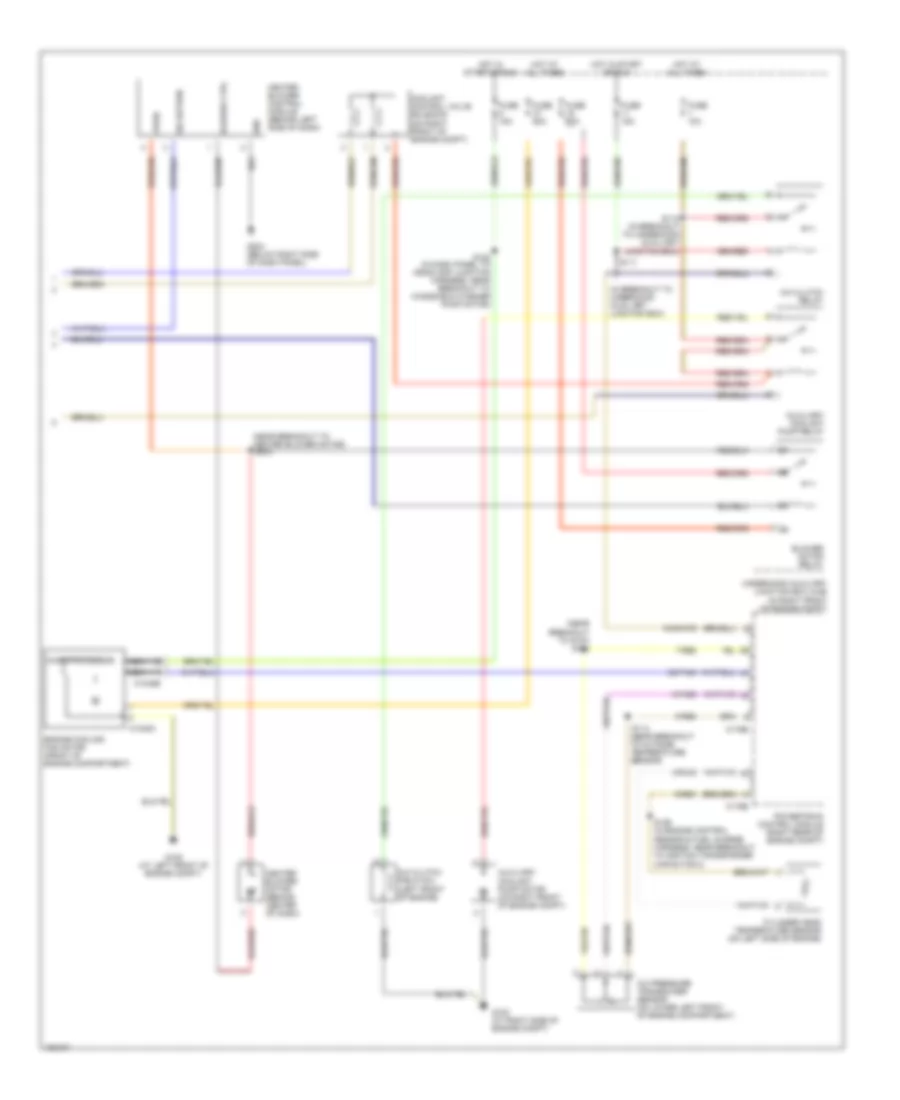
Automatic A/C Wiring Diagram (1 of 2) for Ford Thunderbird 2004

List of elements for Automatic A/C Wiring Diagram (1 of 2) for Ford Thunderbird 2004:
- (in main harness, near breakout to right center image speaker) s214
- (in main harness, near breakout to g200)
- (near breakout to cool air by-pass actuator)
- 10-fa53
- 20-fa10
- 29-fa10
- 31-fa10
- 31s-fa23
- 32-fb2
- 32-fb5
- 32-fb6
- 32-fb7
- 32-fb8
- 33-fb2
- 33-fb5
- 33-fb6
- 33-fb7
- 33-fb8
- 4-fa10
- 5-fa10
- 7-fa1
- 8-fa44
- 8-fa45
- 8-fa47
- 8-fa48
- 8-fa49
- 8-fa51
- 8-fa53
- 8-fb2
- 8-fb5
- 8-fb6
- 8-fb7
- 8-fb8
- 9-fa1
- 9-fa2
- 9-fa3
- 9-fa44
- 9-fa48
- 9-fa49
- 91s-fa76
- 91s-fb3
- 91s-fb4
- 91s-hb7
- Blower motor control
- C228a
- C228b
- C270a
- Central junction box (behind right kick panel)
- Computer data lines system
- Cool air bypass actuator (behind center of dash, on hvac assembly)
- Defogger system
- Defrost mode actuator (behind center of dash, on hvac assembly)
- Electronic automatic temperature control module (behind center of dash)
- Evaporator discharge air temperature sensor (behind center of dash)
- Floor mode actuator (behind center of dash, on hvac assembly)
- Fresh/recirculation door actuator (behind center of dash, on hvac assembly)
- Fuse 10a
- Fuse 5a
- G203 (below right side of dash panel)
- Gnd
- Hot at all times
- Hot in run
- In-vehicle temperature sensor (behind center of dash)
- Left discharge temperature sensor (behind left side of dash)
- Micro- processor
- Motor control
- Near breakout to right center image speaker)
- Outside temperature sensor (on right front of engine compt)
- Panel mode actuator (behind right side of dash, on hvac assembly)
- Right discharge temperature sensor (behind right side of dash)
- S210
- S212 (in main harness, near breakout to passenger air bag module)
- S225
- Scp +
- Scp -
- Sensor return
- Sensor signal
- Sensor signal return
- Sensor voltage
- Signal 2
- Sunload sensor (on top of dash, above glove box)
- Switched (batt/gnd/open)
- Switched gnd
- Twisted pair
- Vbatt
- Vpwr
Automatic A/C Wiring Diagram (2 of 2) for Ford Thunderbird 2004
List of elements for Automatic A/C Wiring Diagram (2 of 2) for Ford Thunderbird 2004:
- (in breakout to underhood auxiliary junction box)
- (near breakout to g103) s104
- (near breakout to heater blower motor)
- 32-pa45
- 7-re8
- 8-fa88
- 8-rj33
- 9-re1
- 9-re8
- 91s-fa79
- A/c clutch field coil (left front of engine)
- A/c clutch relay
- A/c pressure transducer sensor (on lower left front of engine compartment)
- Auxiliary coolant pump motor (on right front of engine compt)
- Auxiliary coolant pump relay
- Blower ctrl
- Blower motor relay
- C1048a
- C1048b
- C175b
- C175e
- Coolant control valve solenoid (on right front of engine compt)
- Cylinder head temperature sensor (on left side of engine)
- Engine cooling fan motor (front of engine compartment)
- Fuse 10a
- Fuse 15a
- Fuse 30a
- Fuse 60a
- G102 (at right side of engine compt)
- G105 (at left front of engine compt)
- G203 (below right side of dash panel)
- Gnd
- Heater blower control module (behind left side of dash)
- Heater blower motor (behind center of dash)
- Hot at all times
- Hot in start or run
- Microprocessor
- Nca
- Powertrain control module (right rear of engine compt)
- S102 (in dash panel to headlamp junction harness, near breakout to windshield washer pump motor)
- S111
- S112 (in breakout to underhood auxiliary junction box)
- S114 (near breakout to outside temperature sensor)
- S126 (in engine control sensor & fuel charge harness, near breakout to ignition transformer capacitor 2)
- S234
- Sig return
- Underhood auxiliary junction box (ajb) (in right front of engine compt)
- Vpwr