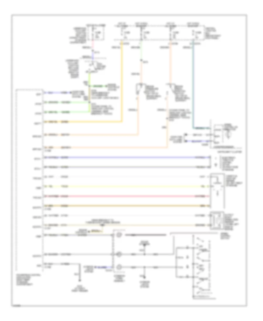
CRUISE CONTROL
Cruise Control Wiring Diagram for Ford Thunderbird 2004
List of elements for Cruise Control Wiring Diagram for Ford Thunderbird 2004:
- (near breakout to turbine shaft speed sensor) s122
- 15s-re21
- 15s-re8
- 29-re8
- 29s-pg1
- 29s-re13
- 31-re25
- 31s-pg24
- 32-rg3
- 33-rg3
- 5-res
- 7-pg24
- 7-rj28
- 8-rj28
- 8-rj39
- 8-ta51
- 87a
- 9-r328
- 9-ta1
- Bpp sig
- Bps sig
- Brake pedal position switch (on top of brake pedal support)
- Brake pressure switch (on top of brake pedal support)
- C175b
- C175e
- C175t
- C218a
- C220b
- C270a
- C270b
- C270d
- Cancel
- Central junction box (behind right kick panel)
- Computer data lines system
- Electronic throttle control motor (on right side of engine)
- Engine controls system
- Etc+/-
- Fuse 40a
- Fuse 5a
- G103 (at right front fender)
- Gnd
- Hot at all times
- Hot in run or start
- Instrument cluster
- Interior lights system
- Microprocessor
- Nca
- Off
- Oss sig
- Output shaft speed (oss) sensor (lower left side of engine)
- Pcm power relay
- Powertrain control module (pcm) (right rear of engine compartment)
- Resume
- S101 (in dash panel to headlamp junction harness, near breakout to g103)
- S109 (near breakout to underhood auxiliary junction box)
- S113
- S218
- Scp+
- Scp-
- Set+
- Set-
- Sig rtn
- Sound systems
- Speed control on indicator
- Speed control switch
- Steering wheel assembly
- Throttle position sensor (on left front of engine)
- Tps sig
- Underhood auxiliary junction box (ajb) (in right front of engine compartment)
- Underhood auxiliary junction box (ajb) (in right front of engine compt)
- Vbatt
- Vpwr
- Vref
 English