ANTI-LOCK BRAKES
Anti-lock Brakes Wiring Diagram for Ford Thunderbird 2004
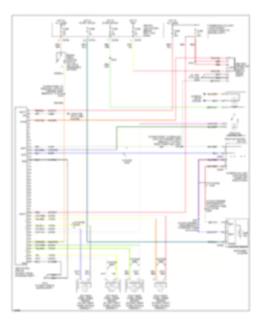
List of elements for Anti-lock Brakes Wiring Diagram for Ford Thunderbird 2004:
- (at left "a" pillar) g202
- (in dash panel to headlamp junction harness, near breakout to g103) s100
- (in dash panel to headlamp junction harness, near breakout to right front park/turn lamp) s108
- (in main harness, near breakout to defrost mode actuator) s206
- 20-cf6a
- 29s-cf58
- 30-cf13
- 30-cf6a
- 31-cf6a
- 31-cf6b
- 31s-cf45
- 4-cf6
- 4-ee6
- 5-cf6
- 7-cf32
- 7-cf34
- 7-cf38
- 7-cf40
- 8-cf32
- 8-cf34
- 8-cf38
- 8-cf40
- 8-cf54
- Abs control module (on right front of engine compt)
- Abs ind
- Abs test connector nca (on left rear of engine compt)
- Brake pedal position switch (on top of brake pedal support)
- C220b
- C270a
- C270b
- C270d
- C283c
- C283d
- Central junction box (behind right kick panel)
- Computer data lines system
- Fuse 30a
- Fuse 40a
- Fuse 5a
- G102 (at right side of engine compt)
- Gnd
- Hot at all times
- Hot in run
- Hot in start or run
- Illum
- Instrument cluster
- Interior auxiliary junction box (under left side of dash)
- Interior lights system
- Iso
- Left front wheel speed sensor (on left front wheel spindle assembly)
- Left rear wheel speed sensor (on left rear wheel spindle assembly)
- Microprocessor
- Red
- Right front wheel speed sensor (on right front wheel spindle assembly)
- Right rear wheel speed sensor (on right rear wheel spindle assembly)
- S120
- S207 (in main harness, near breakout to defrost mode actuator)
- S218
- Scp+
- Scp-
- Traction control off
- Traction control switch
- Twisted pair
- Underhood auxiliary junction box (in right front of engine compt)
- Vbatt
- Vpwr
 English