ELECTRONIC POWER STEERING
Electronic Power Steering Wiring Diagram for Ford Thunderbird 2004

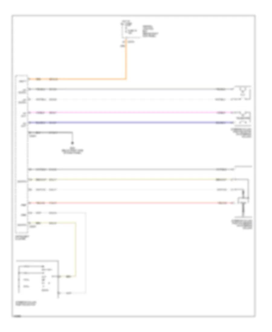
List of elements for Electronic Power Steering Wiring Diagram for Ford Thunderbird 2004:
- (behind seats, on vehicle crossbeam) rear electronic module (rem)
- (right rear of engine compt) powertrain control module
- 29s-dk21
- 31-dk20
- 31s-dk21
- 31s-dk30
- 4-cf6
- 4-eg11
- 4-re8
- 5-cf6
- 5-eg11
- 5-re8
- 8-ce9
- 87a
- 9-ce9
- Abs control module (on right front of engine compt)
- Battery junction box (in luggage compt, near battery)
- C175b
- C201a
- C201b
- C201c
- C270b
- C270d
- C420e
- Central junction box (behind right kick panel)
- Computer data lines system
- Front electronic module (in left "a" pillar)
- Fuse 30a
- Fuse 5a
- G202 (at left "a" pillar)
- Hot at all times
- Power steering valve solenoid (on lower left rear of engine compartment)
- S407 (in body main harness, in breakout to p93)
- Scp +
- Scp -
- Scp+
- Scp-
- Ssp 2 relay
- Twisted pair
- Vpwr
Power Steering Column Wiring Diagram for Ford Thunderbird 2004
List of elements for Power Steering Column Wiring Diagram for Ford Thunderbird 2004:
- 29-al12
- 31-al11
- 32-al6
- 33-al6
- 34-al7
- 35-al7
- 7-al17
- 8-al10
- 8-al16
- 8-al17
- 9-al10
- 9-al17
- C220a
- C220c
- C270a
- Central junction box (behind right kick panel)
- Down
- Fuse 19 15a
- G203 (below right side of dash panel)
- Hot at all times
- In+ out-
- Instrument cluster
- Out
- Sig rtn
- Steering column position motor (on steering column)
- Steering column position sensor (on steering column)
- Steering column position switch
- Telescope
- Tilt
- Up- down+
- Vbatt
- Vref