CRUISE CONTROL
4.9L
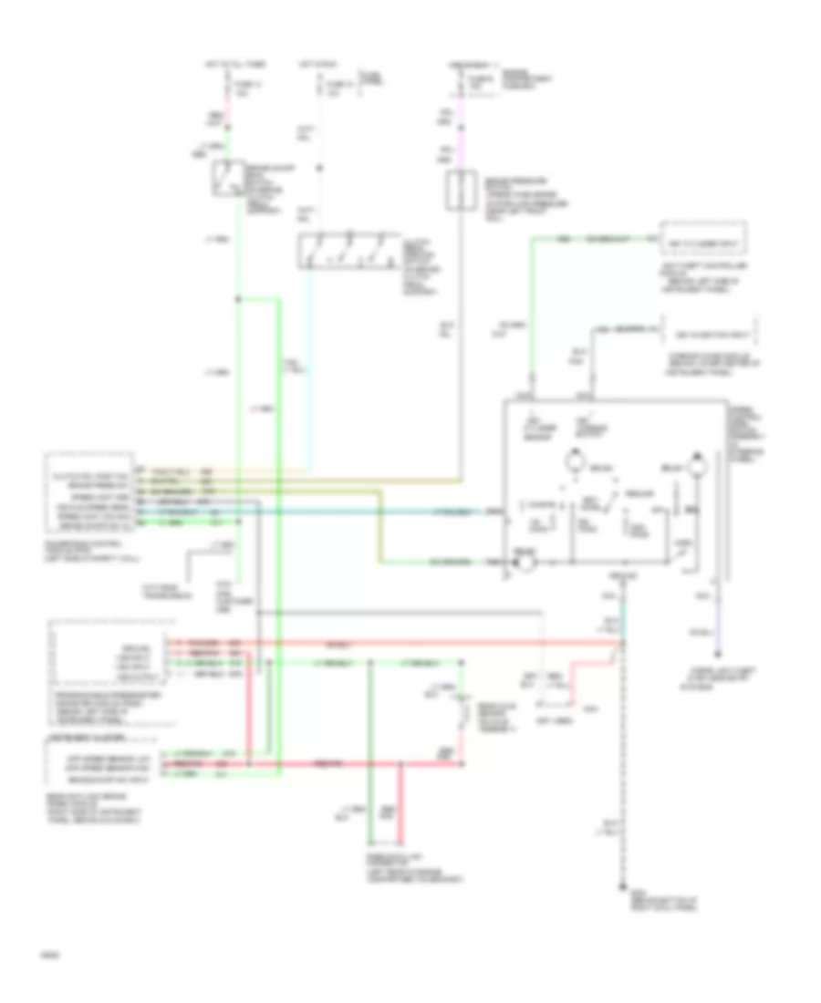
4.9L, Cruise Control Wiring Diagram for Ford Pickup F250 1994

List of elements for 4.9L, Cruise Control Wiring Diagram for Ford Pickup F250 1994:
- (behind bottom of right cowl panel)
- (behind left side of instrument panel, taped to main harness near steering column)
- (behind left side of
- (behind left side of instrument panel)
- (behind lower center of
- (for customer use)
- (left rear of engine compartment,on bracket)
- (left side of engine compartment, near brake master cylinder)
- (left side of safety wall)
- (on axle assembly)
- (on brake pedal support)
- (on brake/ clutch
- (right side of instrument panel, behind glove box)
- 15a
- 5.8l lighting
- A/t
- Accel
- Anti-theft controller
- Brake on/off (boo) switch
- Brake on/off sw in
- Brake on/off sw input
- Brake press input
- Brake pressure switch (opens when brake
- Brush
- Clutch pedal position switch
- Clutch pedal position switch jumper
- Coast
- Cruise control servo/ amplifier assembly
- Cylinder sensor
- Diff speed sensor high
- Diff speed sensor low
- Engine compartment fuse box
- Fuse 13
- Fuse e 15a
- Fuse panel
- G203
- Ground
- Horn
- Horns, anti-theft &
- Hot at all times
- Hot in run
- Instrument cluster
- Instrument panel)
- Key
- Key
- Key cylinder input
- Key-in-ignition input
- Keyless entry
- M/t
- Module
- Nca
- Off
- Ohms
- Pedal support)
- Pnk
- Powertrain control module (pcm)
- Programmable speedometer/ odometer module (psom)
- Rabs data link connector
- Rear anti-lock brake (rabs) module
- Rear axle sensor
- Red
- Red/
- Red/ pnk
- Red/pnk
- Resume
- Set/
- Speed cont sw gnd
- Speed cont sw in
- Speed control/ horn switch assembly (in steering column)
- System has pressure) (near left front rail)
- Systems
- Tan/
- Transmission
- Vehicle power
- Vehicle speed (vss) input
- Vehicle speed input
- Vss input
- Vss output
- Warning chime module
- Warning switch
- With e40d
5.0L
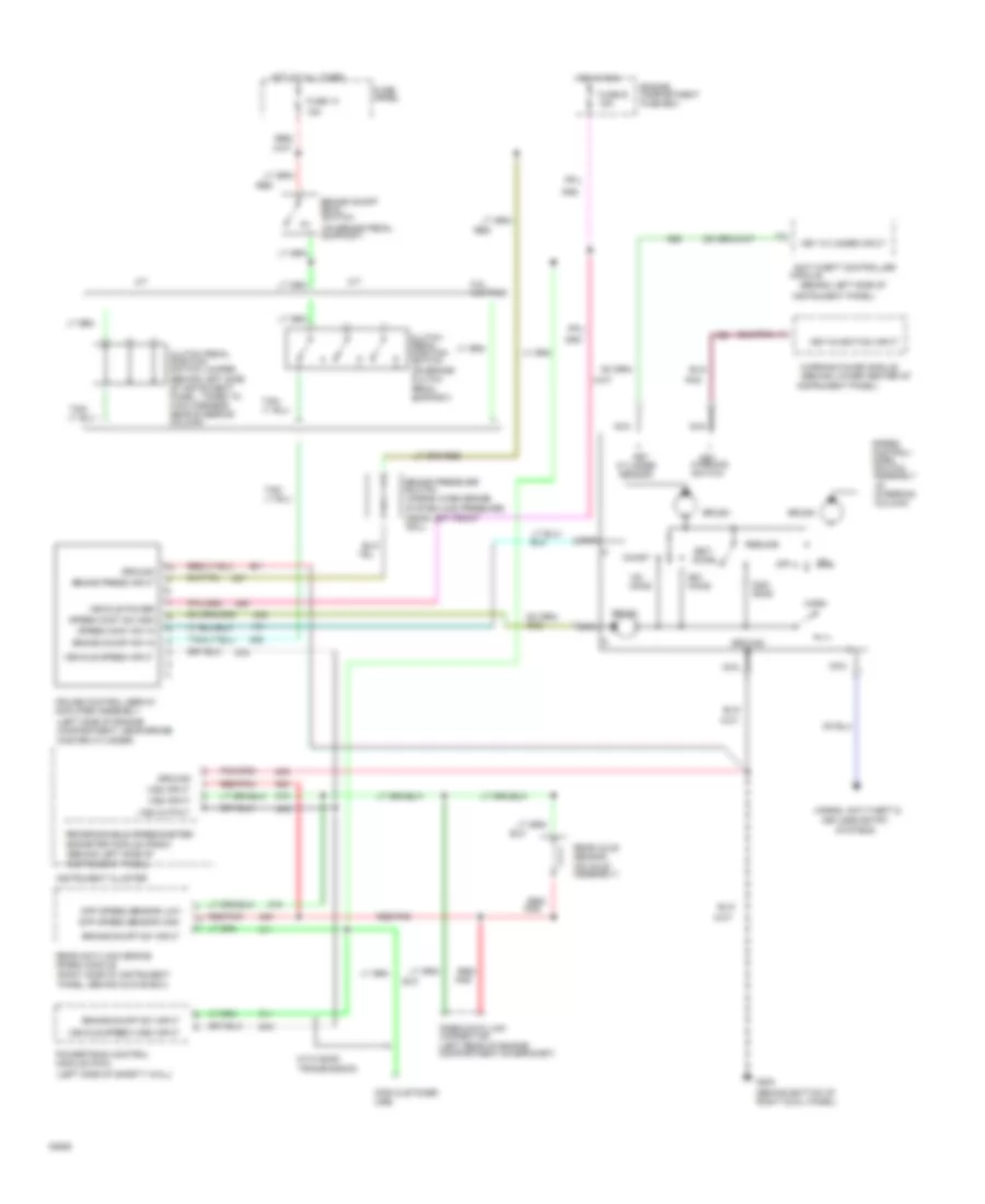
5.0L, Cruise Control Wiring Diagram for Ford Pickup F250 1994
List of elements for 5.0L, Cruise Control Wiring Diagram for Ford Pickup F250 1994:
- (behind bottom of right cowl panel)
- (behind left side of instrument panel, taped to main harness near steering column)
- (behind left side of
- (behind left side of instrument panel)
- (behind lower center of
- (for customer use)
- (left rear of engine compartment,on bracket)
- (left side of engine compartment, near brake master cylinder)
- (left side of safety wall)
- (on axle assembly)
- (on brake pedal support)
- (on brake/ clutch
- (right side of instrument panel, behind glove box)
- 15a
- 5.8l lighting
- A/t
- Accel
- Anti-theft controller
- Brake on/off (boo) switch
- Brake on/off sw in
- Brake on/off sw input
- Brake press input
- Brake pressure switch (opens when brake
- Brush
- Clutch pedal position switch
- Clutch pedal position switch jumper
- Coast
- Cruise control servo/ amplifier assembly
- Cylinder sensor
- Diff speed sensor high
- Diff speed sensor low
- Engine compartment fuse box
- Fuse 13
- Fuse e 15a
- Fuse panel
- G203
- Ground
- Horn
- Horns, anti-theft &
- Hot at all times
- Hot in run
- Instrument cluster
- Instrument panel)
- Key
- Key
- Key cylinder input
- Key-in-ignition input
- Keyless entry
- M/t
- Module
- Nca
- Off
- Ohms
- Pedal support)
- Pnk
- Powertrain control module (pcm)
- Programmable speedometer/ odometer module (psom)
- Rabs data link connector
- Rear anti-lock brake (rabs) module
- Rear axle sensor
- Red
- Red/
- Red/ pnk
- Red/pnk
- Resume
- Set/
- Speed cont sw gnd
- Speed cont sw in
- Speed control/ horn switch assembly (in steering column)
- System has pressure) (near left front rail)
- Systems
- Tan/
- Transmission
- Vehicle power
- Vehicle speed (vss) input
- Vehicle speed input
- Vss input
- Vss output
- Warning chime module
- Warning switch
- With e40d
5.8L
5.8L, Cruise Control Wiring Diagram for Ford Pickup F250 1994
List of elements for 5.8L, Cruise Control Wiring Diagram for Ford Pickup F250 1994:
- (behind bottom of right cowl panel)
- (behind left side of instrument panel, taped to main harness near steering column)
- (behind left side of
- (behind left side of instrument panel)
- (behind lower center of
- (for customer use)
- (left rear of engine compartment,on bracket)
- (left side of engine compartment, near brake master cylinder)
- (left side of safety wall)
- (on axle assembly)
- (on brake pedal support)
- (on brake/ clutch
- (right side of instrument panel, behind glove box)
- 15a
- 5.8l lighting
- A/t
- Accel
- Anti-theft controller
- Brake on/off (boo) switch
- Brake on/off sw in
- Brake on/off sw input
- Brake press input
- Brake pressure switch (opens when brake
- Brush
- Clutch pedal position switch
- Clutch pedal position switch jumper
- Coast
- Cruise control servo/ amplifier assembly
- Cylinder sensor
- Diff speed sensor high
- Diff speed sensor low
- Engine compartment fuse box
- Fuse 13
- Fuse e 15a
- Fuse panel
- G203
- Ground
- Horn
- Horns, anti-theft &
- Hot at all times
- Hot in run
- Instrument cluster
- Instrument panel)
- Key
- Key
- Key cylinder input
- Key-in-ignition input
- Keyless entry
- M/t
- Module
- Nca
- Off
- Ohms
- Pedal support)
- Pnk
- Powertrain control module (pcm)
- Programmable speedometer/ odometer module (psom)
- Rabs data link connector
- Rear anti-lock brake (rabs) module
- Rear axle sensor
- Red
- Red/
- Red/ pnk
- Red/pnk
- Resume
- Set/
- Speed cont sw gnd
- Speed cont sw in
- Speed control/ horn switch assembly (in steering column)
- System has pressure) (near left front rail)
- Systems
- Tan/
- Transmission
- Vehicle power
- Vehicle speed (vss) input
- Vehicle speed input
- Vss input
- Vss output
- Warning chime module
- Warning switch
- With e40d
7.3L
7.3L DI Turbo Diesel, Cruise Control Wiring Diagram for Ford Pickup F250 1994
List of elements for 7.3L DI Turbo Diesel, Cruise Control Wiring Diagram for Ford Pickup F250 1994:
- & keyless entry
- (behind left side of
- (behind left side of instrument panel)
- (behind lower center of
- (for customer use)
- (in steering wheel)
- (left rear of engine compartment,on bracket)
- (left side of safety wall)
- (not used)
- (on axle assembly)
- (on brake/ clutch
- (right side of instrument panel, behind glove box)
- 10a
- 15a
- 29
- Accel
- Anti-theft controller
- Brake on/off (boo) switch (on brake clutch pedal support)
- Brake on/off sw in
- Brake on/off sw input
- Brake press sw
- Brake pressure switch (opens when brake
- Brush
- Cio4
- Clutch pedal position switch
- Clutch pdl posit sw
- Coast
- Cylinder
- Diff speed sensor high
- Diff speed sensor low
- Engine compartment fuse box
- Fuse 13
- Fuse 18
- Fuse e 15a
- Fuse panel
- G203 (behind bottom of right cowl panel)
- Ground
- Horn
- Horns, anti-theft
- Hot at all times
- Hot in run
- Instrument cluster
- Instrument panel)
- Key
- Key
- Key cylinder input
- Key-in-ignition input
- Module
- Nca
- Off
- Ohms
- Pedal support)
- Pnk
- Powertrain control module (pcm)
- Programmable speedometer/ odometer module (psom)
- Rabs data link connector
- Rear anti-lock brake (rabs) module
- Rear axle sensor
- Red
- Red/
- Red/ pnk
- Red/pnk
- Resume
- Sensor
- Set/
- Speed cont com sig
- Speed cont gnd
- Speed control/ horn switch assembly
- Switch
- System has pressure) (near left front rail)
- Systems
- Tan/
- Transmission
- Vehicle speed sens
- Vss input
- Vss output
- Warning
- Warning chime module
- With e40d
7.3L IDI Diesel, Cruise Control Wiring Diagram for Ford Pickup F250 1994
List of elements for 7.3L IDI Diesel, Cruise Control Wiring Diagram for Ford Pickup F250 1994:
- (behind bottom of right cowl panel)
- (behind left side of instrument panel, taped to main harness near steering column)
- (behind left side of
- (behind left side of instrument panel)
- (behind lower center of
- (for customer use)
- (left rear of engine compartment,on bracket)
- (left side of engine compartment, near brake master cylinder)
- (left side of safety wall)
- (on axle assembly)
- (on brake pedal support)
- (on brake/ clutch
- (right side of instrument panel, behind glove box)
- 15a
- 5.8l lighting
- A/t
- Accel
- Anti-theft controller
- Brake on/off (boo) switch
- Brake on/off sw in
- Brake on/off sw input
- Brake press input
- Brake pressure switch (opens when brake
- Brush
- Clutch pedal position switch
- Clutch pedal position switch jumper
- Coast
- Cruise control servo/ amplifier assembly
- Cylinder sensor
- Diff speed sensor high
- Diff speed sensor low
- Engine compartment fuse box
- Fuse 13
- Fuse e 15a
- Fuse panel
- G203
- Ground
- Horn
- Horns, anti-theft &
- Hot at all times
- Hot in run
- Instrument cluster
- Instrument panel)
- Key
- Key
- Key cylinder input
- Key-in-ignition input
- Keyless entry
- M/t
- Module
- Nca
- Off
- Ohms
- Pedal support)
- Pnk
- Powertrain control module (pcm)
- Programmable speedometer/ odometer module (psom)
- Rabs data link connector
- Rear anti-lock brake (rabs) module
- Rear axle sensor
- Red
- Red/
- Red/ pnk
- Red/pnk
- Resume
- Set/
- Speed cont sw gnd
- Speed cont sw in
- Speed control/ horn switch assembly (in steering column)
- System has pressure) (near left front rail)
- Systems
- Tan/
- Transmission
- Vehicle power
- Vehicle speed (vss) input
- Vehicle speed input
- Vss input
- Vss output
- Warning chime module
- Warning switch
- With e40d
7.5L
7.5L, Cruise Control Wiring Diagram for Ford Pickup F250 1994
List of elements for 7.5L, Cruise Control Wiring Diagram for Ford Pickup F250 1994:
- (behind bottom of right cowl panel)
- (behind left side of instrument panel, taped to main harness near steering column)
- (behind left side of
- (behind left side of instrument panel)
- (behind lower center of
- (for customer use)
- (left rear of engine compartment,on bracket)
- (left side of engine compartment, near brake master cylinder)
- (left side of safety wall)
- (on axle assembly)
- (on brake pedal support)
- (on brake/ clutch
- (right side of instrument panel, behind glove box)
- 15a
- 5.8l lighting
- A/t
- Accel
- Anti-theft controller
- Brake on/off (boo) switch
- Brake on/off sw in
- Brake on/off sw input
- Brake press input
- Brake pressure switch (opens when brake
- Brush
- Clutch pedal position switch
- Clutch pedal position switch jumper
- Coast
- Cruise control servo/ amplifier assembly
- Cylinder sensor
- Diff speed sensor high
- Diff speed sensor low
- Engine compartment fuse box
- Fuse 13
- Fuse e 15a
- Fuse panel
- G203
- Ground
- Horn
- Horns, anti-theft &
- Hot at all times
- Hot in run
- Instrument cluster
- Instrument panel)
- Key
- Key
- Key cylinder input
- Key-in-ignition input
- Keyless entry
- M/t
- Module
- Nca
- Off
- Ohms
- Pedal support)
- Pnk
- Powertrain control module (pcm)
- Programmable speedometer/ odometer module (psom)
- Rabs data link connector
- Rear anti-lock brake (rabs) module
- Rear axle sensor
- Red
- Red/
- Red/ pnk
- Red/pnk
- Resume
- Set/
- Speed cont sw gnd
- Speed cont sw in
- Speed control/ horn switch assembly (in steering column)
- System has pressure) (near left front rail)
- Systems
- Tan/
- Transmission
- Vehicle power
- Vehicle speed (vss) input
- Vehicle speed input
- Vss input
- Vss output
- Warning chime module
- Warning switch
- With e40d